National Instruments NI 5422 User Manual
Page 5
© National Instruments Corporation
5
NI 5422 Specifications
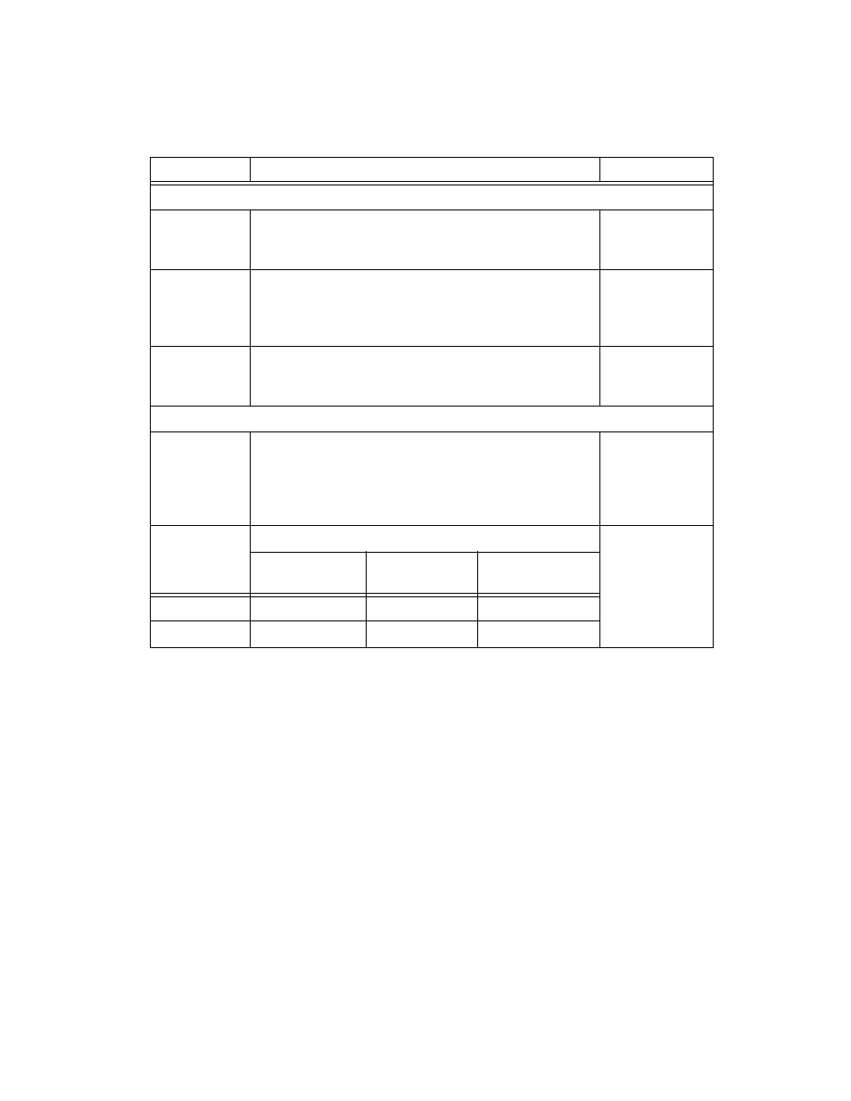
Output Characteristics (Continued)
Output Enable
Software-selectable. When the Output Path is disabled, the
CH 0 Output is terminated to ground with a 1 W resistor
equal to the selected output impedance.
—
Maximum
Output
Overload
The CH 0 output can be connected to a 50
Ω, ±12 V
(±8 V for the Direct Path) source without sustaining any
damage. No damage occurs if the CH 0 output is shorted to
ground indefinitely.
—
Waveform
Summing
The CH 0 output supports waveform summing among
similar paths—specifically, the outputs of multiple NI 5422
signal generators can be connected directly together.
—
Frequency and Transient Response
Analog
Filter
Software-selectable 7-pole elliptical filter for image
suppression.
Available on
Low-Gain
Amplifier and
High-Gain
Amplifier Paths.
Pulse
Response
Path
Values are
typical. Analog
Filter disabled.
Measured with a
1 m RG-223
cable.
Direct
Low-Gain
Amplifier
High-Gain
Amplifier
Rise/Fall Time
1.0 ns
2.1 ns
4.8 ns
Aberration
16%
6%
8%
Table 1. (Continued)
Specification
Value
Comments