Markers – National Instruments NI 5422 User Manual
Page 25
© National Instruments Corporation
25
NI 5422 Specifications
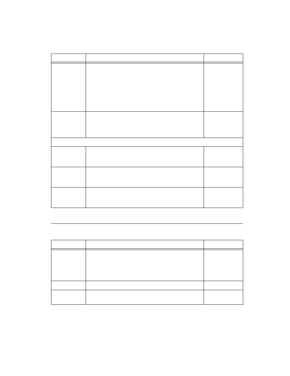
Markers
Delay from
Start Trigger to
CH 0 Analog
Output
65 Sample Clock Periods + 110 ns
Refer to t
s2
at
NI Signal
Generators
Help»Devices»
NI 5422»
NI PXI-5422»
Triggering»
Trigger Timing.
Delay from
Start Trigger to
Digital Data
Output
41 Sample Clock periods + 110 ns
—
Trigger Exporting
Exported
Trigger
Destinations
A signal used as a trigger can be routed out to any
destination listed in the Destinations specification
of Table 9.
—
Exported
Trigger Delay
65 ns (typical). Refer to t
s3
at NI Signal Generators Help»
Devices»NI 5422»NI PXI-5422»Triggering»Trigger
Timing.
—
Exported
Trigger Pulse
Width
>150 ns. Refer to t
s4
at NI Signal Generators Help»
Devices»NI 5422»NI PXI-5422»Triggering»Trigger
Timing.
—
Table 9.
Specification
Value
Comments
Destinations
1. PFI<0..1> (SMB front panel connectors)
2. PFI<4..5> (DIGITAL DATA & CONTROL front panel
connector)
3. PXI_Trig<0..6> (backplane connector)
—
Quantity
One Marker per Segment.
—
Quantum
Marker position must be placed at an integer multiple of
four samples.
—
Table 8. (Continued)
Specification
Value
Comments