Figure 22. main q1 menu structure – Nokia DNT2Mi-fp User Manual
Page 48
DNT2Mi-fp Data Network Terminal User manual
48 (60)
© Nokia Corporation
DN0445814
Nokia Proprietary and Confidential
Issue 2-0 en
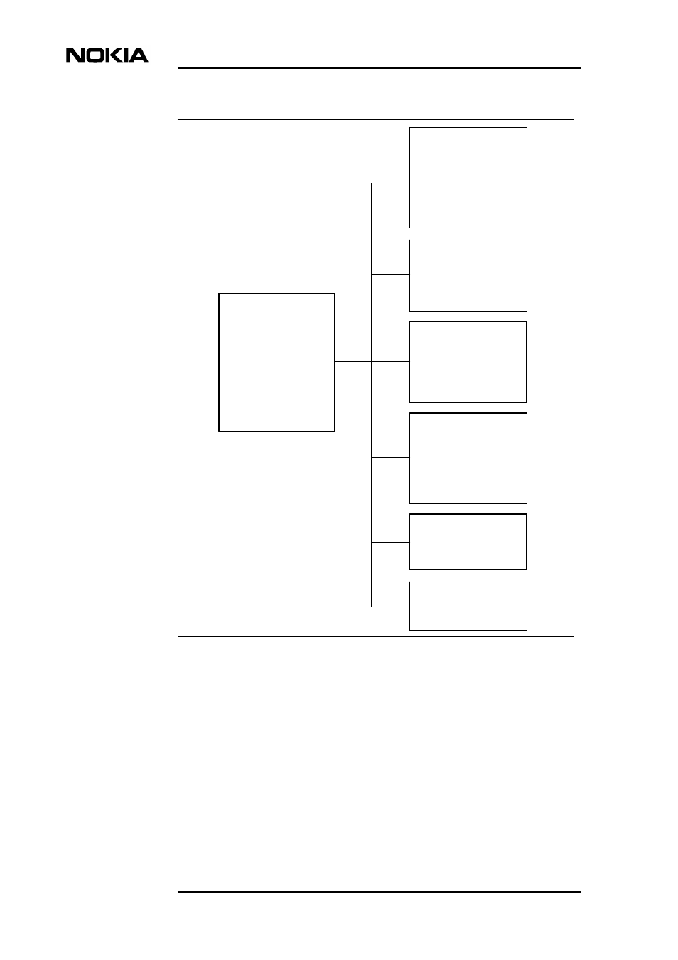
Figure 22.
Main Q1 menu structure
1 Fault display
3 Reset local cancel *)
4 Identifications
5 Controls
6 Settings
7 Measurements
8 Statistics
9 Testing *)
10 User privileges
11 Miscellaneous *)
4
DNT-fp Identifications:
0 Display
1 Eq type
2 Eq name
4 Installation info
5 HW version
6 SW version
7 Modify
8 Serial number
DNT-fp controls:
0 Display
1 All test loops off
2 Port test loop
3 Line test loop
4 Self test
5
DNT-fp settings:
0 Display
1 Service options
2 Timing source
3 Line settings
4 Port settings
7 Load factory settings
6
DNT-fp measurements:
0 Display all
1 Noise margins
2 Rx levels
3 Tx levels
4 Attenuations
5 Supply voltage
6 Temperature
7
DNT-fp statistics:
8
DNT-fp privileges:
1 Password for privileges
3 Cancel privileges
4 Setting parameters
10
*) not implemented
1 Port statistics
2 Line statistics
3 System counters
99 Reset all statistics
2 Local alarm cancel *)