Parts guide, Figure 5 mrz-6 features – Niles Audio MRZ-6 User Manual
Page 6
Parts Guide
4
COMMON
+ -
+ -
+ -
ZONE
ALL ON
UART
MODES
ROOM 1
OUTPUT
ROOM 2
OUTPUT
ROOM 3
OUTPUT
ROOM 4
OUTPUT
ROOM 5
OUTPUT
ROOM 6
OUTPUT
DEFAULTS
L
R
L
R
L
R
L
R
L
R
L
R
G
N
D
1
D
A
T
A
+
1
2
V
IN
+ -
OUT
+ -
FLASHERS
IR DATA
DEDI-
CATED
+ -
G
N
D
2
D
A
T
A
+
1
2
V
G
N
D
3
D
A
T
A
+
1
2
V
G
N
D
4
D
A
T
A
+
1
2
V
G
N
D
5
D
A
T
A
+
1
2
V
G
N
D
6
D
A
T
A
+
1
2
V
IR SENSOR/KEYPAD INPUT
V E
COMMON
ZONE
ALL ON
CTRL
OUT
POWER
16VAC
FLASHER
LEVEL
ADJUST
1
G
N
D
D
A
T
A
+
1
2
V
2
G
N
D
D
A
T
A
+
1
2
V
3
G
N
D
D
A
T
A
+
1
2
V
4
G
N
D
D
A
T
A
+
1
2
V
5
G
N
D
D
A
T
A
+
1
2
V
6
G
N
D
D
A
T
A
+
1
2
V
IN
OUT
FLASHERS
IR DATA
DEDI-
CATED
12V
SYNC
IR SENSOR/KEYPAD INPUTS
V E
NILES
UART
+ -
MAIN
INPUT
ROOM 1
OUTPUT
ROOM 2
OUTPUT
ROOM 3
OUTPUT
ROOM 4
OUTPUT
ROOM 5
OUTPUT
ROOM 6
OUTPUT
L
R
L
R
L
R
L
R
CASCADE
OUTPUT
L
R
L
R
L
R
L
R
Niles Audio Corporation, Inc.
Miami, Florida USA
MODEL MRZ-6
This device complies with part 15 of the FCC Rules. Operation is sub-
ject to the following two conditions: (1) This device may not cause
harmful interference, and (2) this device must accept any interference
received, including interference that may cause undesired operation.
ALL OFF button turns off your
entire system; including the
preamp/receiver and connect-
ed components.
ON/OFF and VOLUME con-
trols affect rooms which are
“selected” (LEDs are blinking)
CONFIRM LED flashes green
whenever an IR signal or
interference is received from any
IR sensor
TEACHING LED teaches Niles
IR commands to any learning
remote control
ALL ON button enables
you to turn on all or some
of your rooms depending
upon the rear panel DIP
switch settings
INFRARED
SENSOR
controls Room 1
and connected
IR components
ROOM STATUS LEDs.
LED BLINKING
- The room is selected; you may adjust
volume, room on/off, etc. using the front panel controls
LED on - The room is on
LED off - The room is off
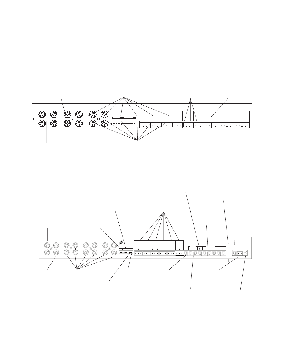
RCA Jack Input con-
nect to a record output,
a preamp output or a
multiroom output of
your preamp/receiver.
EYE DIP switch enables
the front panel IR sensor
CONTROL OUT
provides 12V DC
@ 200mA when
one or more
speakers are
turned on
POWER jack
for 16V AC
wall adapter
(included)
COMMON
FLASHER outputs
control components
which are common
to all MRZ-6’s in a
system
IR DATA IN and Out
connects to other IR sys-
tems (MRZ-6, IRP2+,
IRP6+, IRZ6+, etc.)
SENSOR/KEYPAD
connections corre-
sponding to each of
the Room line level
volume controls.
VOLUME DIP
chooses whether
all rooms will turn
on at 25% or at
the last volume
setting used
MODE switches control the
configuration of multiple MRZ-6’s
and the routing of IR Data
FLASHER level
adjusts the power
of all flashers
DEDICATED FLASHER
output controls compo-
nents which are dedicat-
ed to this MRZ-6
UART jack for ALL ON and
ALL OFF commands when
multiple MRZ-6’s are used
within one system
ALL-ON DIP switches enable you to select
which rooms are activated when the ALL-ON
command is issued
RCA Jack Cascade
Outputs
connect to the Inputs
of additional MRZ-6s.
RCA Jack Outputs
connect to the Inputs
of the power ampli-
fiers for each room.
Figure 5 MRZ-6 features
ROOM SELECT buttons allow you to “select”
rooms singly or in combinations. Once a room(s) is
selected, you may control it with the ON/OFF and
VOLUME UP and VOLUME DOWN buttons
SYNC jack
for 12V DC
power status
from
preamp/receiver