Wiring diagrams for infrared control, 1 2 v, Cascade output – Niles Audio MRZ-6 User Manual
Page 13: Niles audio corporation, inc. miami, florida usa
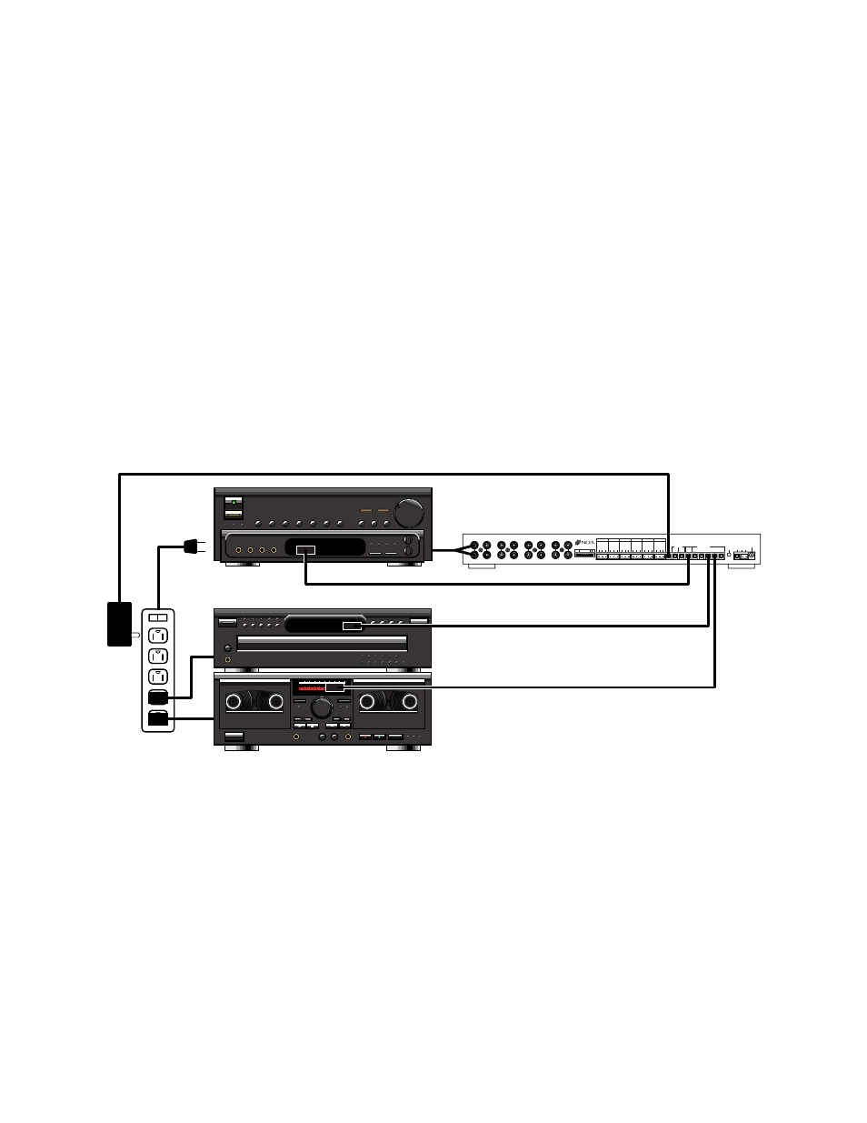
Wiring Diagrams for Infrared Control
IR Connections for a System with a Dedicated Preamp/Receiver and one MRZ-6
As explained on page 6, a single zone system with one MRZ-6 will distribute the output of one Preamp/Receiver’s
selected audio source to each of its six outputs for amplification and individual volume control. See Figure 16.
• A 12V DC wall adapter is connected to the switched outlet of the Preamp/Receiver to provide sync (or
status) to the MRZ-6. This switched outlet may also be used to power up source components which have
latching power.
• Both ZONE DIP switches should be set to the UP (or single zone) position. All IR codes are passed through
both the MRZ-6’s Dedicated and Common flasher outputs.
• When using RP-9 keypads, all automation codes are taught to the MRZ-6.
For more information concerning IntelliPad®/MRZ-6 programming, see page 26 of the MRZ-6 manual.
11
0 1 0 : 0 0
O O : 0 0
O O : 0 0
93.9 FM
STEREO
COMMON
ZONE
ALL ON
CTRL
OUT
POWER
16VAC
FLASHER
LEVEL
ADJUST
1
G
N
D
D
A
T
A
+
1
2
V
2
G
N
D
D
A
T
A
+
1
2
V
3
G
N
D
D
A
T
A
+
1
2
V
4
G
N
D
D
A
T
A
+
1
2
V
5
G
N
D
D
A
T
A
+
1
2
V
6
G
N
D
D
A
T
A
+
1
2
V
IN
OUT
FLASHERS
IR DATA
DEDI-
CATED
12V
SYNC
IR SENSOR/KEYPAD INPUTS
V E
UART
+ -
MAIN
INPUT
ROOM 1
OUTPUT
ROOM 2
OUTPUT
ROOM 3
OUTPUT
ROOM 4
OUTPUT
ROOM 5
OUTPUT
ROOM 6
OUTPUT
L
R
L
R
L
R
L
R
CASCADE
OUTPUT
L
R
L
R
L
R
L
R
Niles Audio Corporation, Inc.
Miami, Florida USA
MODEL MRZ-6
This device complies with part 15 of the FCC Rules. Operation is sub-
ject to the following two conditions: (1) This device may not cause
harmful interference, and (2) this device must accept any interference
received, including interference that may cause undesired operation.
Figure 16 IR Connections for a System with a Dedicated Preamp/Receiver and one MRZ-6
To switched outlet
From tape or pre-out