Setting the dip switches – Niles Audio MRZ-6 User Manual
Page 21
19
Setting the DIP Switches
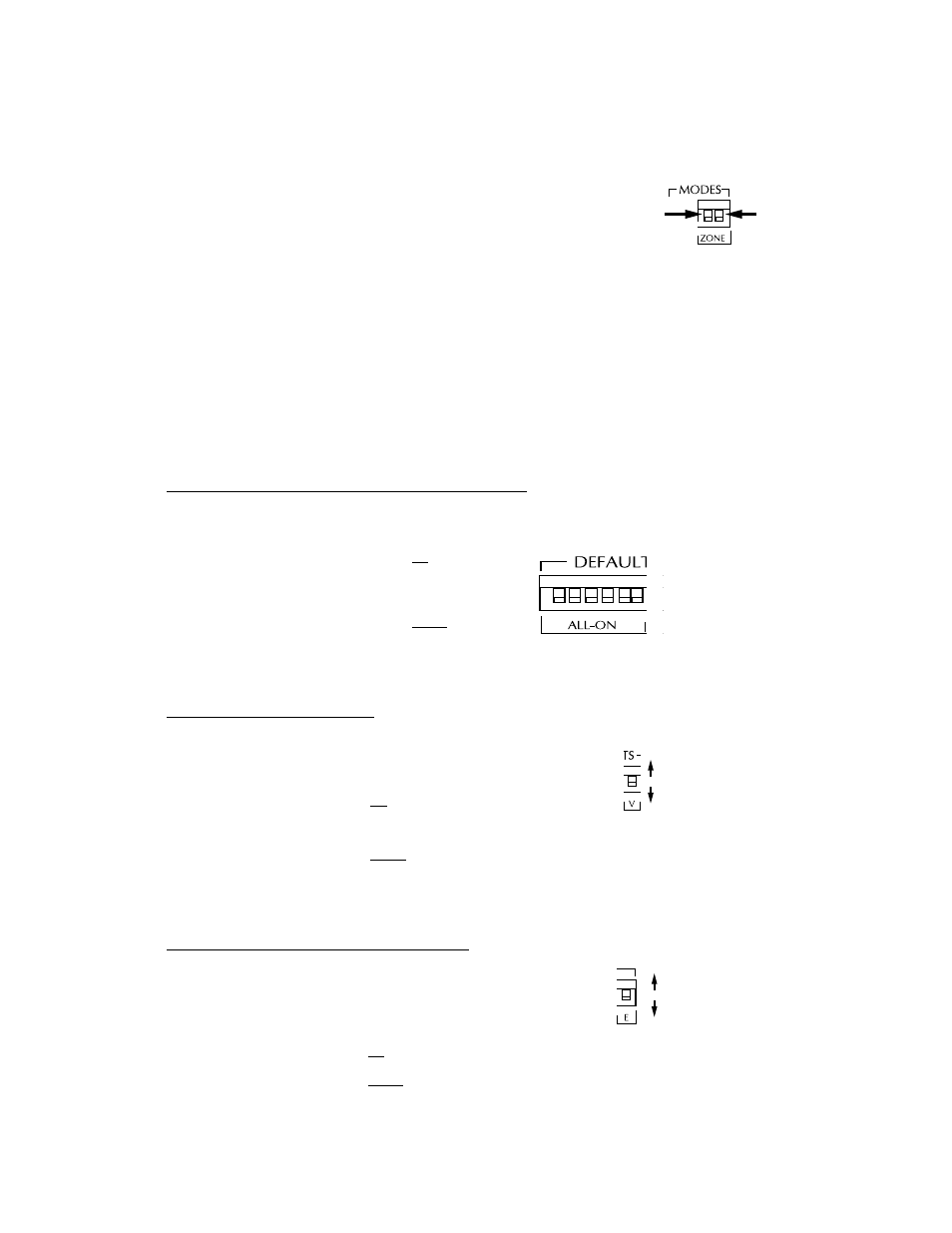
The ZONE DIP Switch
In a single zone system (a system with one preamp/receiver selecting
sources), both the Zone switches are in the UP position. In this position, if
additional MRZ-6’s are added to the system, the IR commands from other
MRZ-6’s will be routed to the Dedicated Flasher.
In a multiple zone system, both the switches are set to the DOWN position.
In this position, the IR commands from other MRZ-6’s will not be routed to
the dedicated flasher, enabling identical preamp/receivers to be simultane-
ously controlled by each MRZ-6. See Figure 22.
Setting the DEFAULT DIP Switches
The DEFAULT DIP switches are used to configure various features of the MRZ-6.
Choosing Rooms That Respond To An ALL ON Command
The DIP switches labeled ALL ON enable you to individually configure which rooms will respond to the ALL
ON command. See Figure 23. Each room has a corresponding DIP switch (1-6 starting from the left).
• Setting the ALL ON DIP switch in the up position will
enable the corresponding room control module to
respond to an ALL ON command.
• Setting the ALL ON DIP switch in the down position will
disable the corresponding room control module from
responding to an ALL ON command.
Setting the Turn-On Volume Level
The DIP switch labeled V enables you configure the volume level when
a room is turned on. See Figure 24.
• Setting the V DIP switch in the up position will enable a room, when
turned on, to automatically revert to its previous volume level.
• Setting the V DIP switch in the down position will enable a room,
when turned on, to automatically play at 25% of the maximum
volume level.
Enabling/Disabling the MRZ-6’s Built-In IR Sensor
In some installations, having the built-in IR sensor enabled will cause a
feedback loop. The DIP switch labeled E disables the MRZ-6 sensor.
See Figure 25.
• Setting the E DIP switch in the up position enables the IR sensor.
• Setting the E DIP switch in the down position disables the IR sensor.
Controls DA
to DEDICAT
ontrols DATA IN
control module
Figure 22 In a single zone system, both Zone
DIP switches are in the UP position.
Multi Zone
Both switches
are in the
DOWN position.
Single Zone
Both switches
are in the UP
position.
UP = Responds To ALL ON
DOWN = Ignores ALL On
Figure 23 ALL ON respond DIP switches.
1 2 3 4 5 6
Turn on with last volume setting
Turn on with 25% volume
Figure 24 Turn-on volume level.
Enables built-in IR sensor
Disables built-in IR sensor
Figure 25
Enable/Disable switch for
MRZ-6’s IR Sensor