Niles Audio MRZ-6 User Manual
Page 18
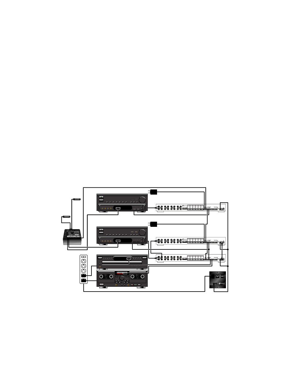
IR Connections for a System with two Dual Zone Receivers and multiple MRZ-6’s
This system is very similar to the dual zone receiver/single MRZ-6 system. Two separate home theaters and two sepa-
rate zones of multi-room sound may be controlled independently. See Figure 21.
• It is not necessary to sync the receiver if the second zone has dedicated “on” and “off” commands or can
be activated with an input select command. Note: If the dual zone receiver you are using has a control volt-
age output or a switched outlet which is active ONLY when the second zone is on, the second zone may
be synced. However, if the second zone does not have discrete "on" and "off" commands, or the ability to
turn on with an input select command as described above, the receiver cannot be automated.
• If IR sensors are required to operate the main zone of the home theaters, sensors must be connected to an
IRZ-6+ IR Main System Unit with flashers to control the home theaters via their receivers front panel.
• IR sensors and an IRZ-6+ are used to enable control of the main zones of each receiver via the IRZ’s
Dedicated flasher outputs to their front panels.
• The DATA OUT of the IRZ-6+ is connected to the DATA IN of the first Slave MRZ #1. The DATA IN/OUT
connections of the other MRZ-6’s connect to the Master MRZ-6 #3 which flashes the source components
via its Common flasher outputs.
• The UART connection enables the Slave MRZ-6’s to power on the Preamp/Receiver using the automation
codes taught to the Master MRZ-6. The UART connection enables All On and All Off commands to control
all of the rooms common to Master MRZ-6 #3 and Slave MRZ-6 #2 only. For more information, see page 8
of the MRZ-6 manual.
16
0 1 0 : 0 0
O O : 0 0
O O : 0 0
93.9 FM
STEREO
93.9 FM
STEREO
COMMON
ZONE
ALL ON
CTRL
OUT
POWER
16VAC
FLASHER
LEVEL
ADJUST
1
G
N
D
D
A
T
A
+
1
2
V
2
G
N
D
D
A
T
A
+
1
2
V
3
G
N
D
D
A
T
A
+
1
2
V
4
G
N
D
D
A
T
A
+
1
2
V
5
G
N
D
D
A
T
A
+
1
2
V
6
G
N
D
D
A
T
A
+
1
2
V
IN
OUT
FLASHERS
IR DATA
DEDI-
CATED
12V
SYNC
IR SENSOR/KEYPAD INPUTS
V E
UART
+ -
MAIN
INPUT
ROOM 1
OUTPUT
ROOM 2
OUTPUT
ROOM 3
OUTPUT
ROOM 4
OUTPUT
ROOM 5
OUTPUT
ROOM 6
OUTPUT
L
R
L
R
L
R
L
R
CASCADE
OUTPUT
L
R
L
R
L
R
L
R
Niles Audio Corporation, Inc.
Miami, Florida USA
MODEL MRZ-6
This device complies with part 15 of the FCC Rules. Operation is sub-
ject to the following two conditions: (1) This device may not cause
harmful interference, and (2) this device must accept any interference
received, including interference that may cause undesired operation.
IN
OUT
+ —
+ —
Figure 21 IR Connections for a System with two Dual Zone Receivers and multiple MRZ-6’s
From Multiroom pre-out
To switched outlet
To CONTROL IN
To switched outlet
From Multiroom pre-out
Master MRZ-6
Slave MRZ-6
Niles AC-3
Master MRZ-6
To Multiroom IR input
To Multiroom IR input
Home
Theater
Sensor
#1
Home
Theater
Sensor
#2
#1
#2
#3