Figure 2-2. scc-b switch 4, Figure 2-3. connector 4 (cn4) strapping, sync unit, Attach the sync unit to the cpc-ex card – Philips T-SMART DBS-EX23-530 User Manual
Page 33
Installation
Installation Procedures
Revised April 2000
DBS-EX23-530
2-15
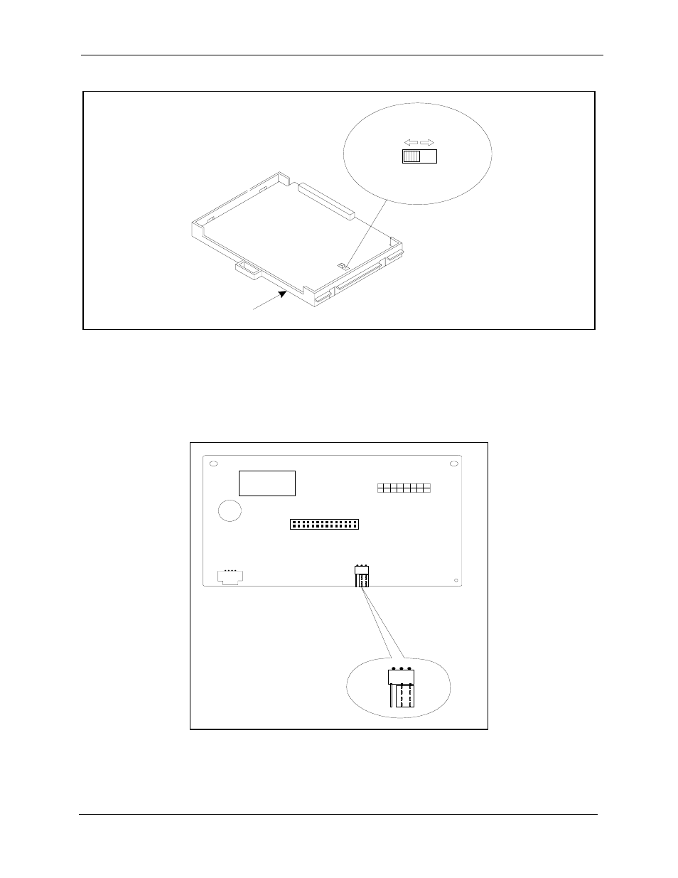
Figure 2-2. SCC-B Switch 4
3. Check connector 4 (CN4) on the Sync Unit (VB-43563). Make sure that
Pins 2 and 3 are strapped. (See Figure 2-3.)
When Pins 2 and 3 are strapped, the Sync Unit synchronizes the DBS
ISDN card with the signaling provided by the public network.
Figure 2-3. Connector 4 (CN4) strapping, Sync Unit
4. Attach the Sync Unit to the CPC-EX card.
(C PC -B
C PC -EX)
(C PC -A
C PC -A II)
SW 4
SC C -B C ard
M ode B
M ode A
C N 2
C N 3
C N 1
C N 4
Free
N et
1
3
See also other documents in the category Philips Phones:
- KX-TAW848 (128 pages)
- Line Cord SWL6146 (2 pages)
- DECT211 (20 pages)
- VOIP3211G/37 (2 pages)
- CD 155 (46 pages)
- CD6451B/37 (1 page)
- 380 Vox (48 pages)
- TD6626/BE (61 pages)
- skip 100 (2 pages)
- Zenia Voice 6326 (64 pages)
- SE4502B/17 (6 pages)
- SWL4165 (2 pages)
- CD4502B/17 (59 pages)
- D711 (87 pages)
- SE 745 (2 pages)
- VOICESONIC KX-T7667 (8 pages)
- DECT511 (67 pages)
- DECT2250 (57 pages)
- CD1552B/17 (2 pages)
- HALO SURFACE H2240 (12 pages)
- Zenia 6825 (1 page)
- Kala Plus 200 (7 pages)
- 9850 (88 pages)
- Coil Cord US2-P70054 (2 pages)
- Wall Jack SDJ6000W (2 pages)
- Coil Cord US2-P70051 (2 pages)
- VOIP1511B (2 pages)
- XL3402 (32 pages)
- SE6590B/37 (29 pages)
- SJA9190/17 (33 pages)
- CD 145 (6 pages)
- 954 (32 pages)
- SOPHO iSMobile C244 (43 pages)
- D750 (33 pages)
- Xalio 200 (17 pages)
- MAGIC 5 MAGIC5 (32 pages)
- KX-TEA308 (168 pages)
- SWL6120 (2 pages)
- DECT 122 (27 pages)
- SWL6163W (2 pages)
- VOIP 080 (15 pages)
- VOIP321 (44 pages)
- SE 7450 (31 pages)
- SE659 (76 pages)