Part names 04 – Pioneer PDP-507XD User Manual
Page 15
15
En
Part Names
04
En
gl
is
h
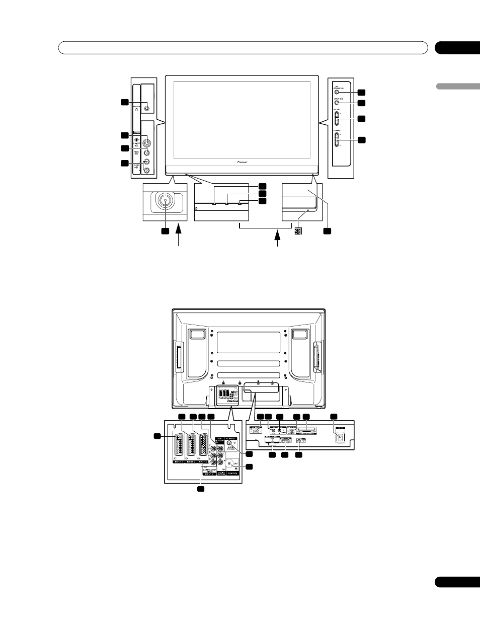
1 PC INPUT terminal (ANALOG RGB)
2 ANT OUT terminal (Antenna through out)
3 ANT IN terminal (Antenna in for DTV)
•
Power can be supplied through this terminal
4 DIGITAL OUT terminal (OPTICAL)
5 COMMON INTERFACE slot
•
For a CA Module with a smart card
6 AC IN terminal
7 INPUT 3/INPUT 4 terminals (HDMI)
8 RS-232C terminal (used for factory setup)
9 ANT (Antenna) input terminal
10 INPUT 1 terminal (SCART)
11 INPUT 2 terminal (SCART)
12 INPUT 3 terminal (SCART)
13 INPUT 2 terminals (COMPONENT VIDEO: Y, P
B
, P
R
)
14 SUB WOOFER OUTPUT terminal
15 AUDIO OUTPUT terminals
16 PC INPUT terminal (AUDIO)
17 CONTROL OUT terminal
6
8
9
7
10
12
11
13
5
1
TIMER
ON
STANDBY
POWER
4
3
2
Front view
(PDP-427XD)
Viewed from below of the display
Viewed from the front side of the display
1 POWER button
2 POWER ON indicator
3 STANDBY indicator
4 TIMER indicator
5 Remote control sensor
(Side view)
6 STANDBY/ON button
7 INPUT button
8 VOLUME +/– buttons
9 CHANNEL +/– buttons
10 PHONES output terminal
11 INPUT 5 terminal (S-VIDEO)
12 INPUT 5 terminal (VIDEO)
13 INPUT 5 terminals (AUDIO)
3
4
1
3
8
7
6
9
17
16
10
14
12 13
11
15
4 5
2
Rear view
(PDP-427XD)
(Terminals located on the upper edge of the
compartment)