Paradyne 3551 User Manual
Page 16
14
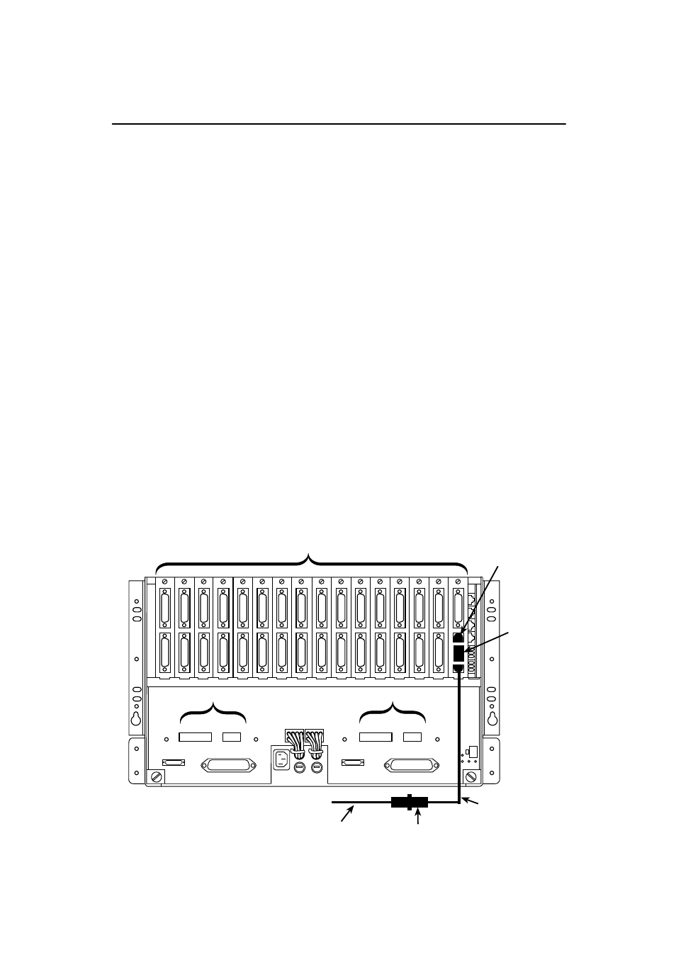
7. At the rear of the carrier, connect the appropriate DTE interface cable (EIA-232-D
or V.35) to the rear connector plate. For an EIA-232-D interface cable, connect the
EIA-232-D cable to the top DTE connector on the rear connector plate.
For the 25-pin V.35 interface, a V.35 interconnect cable is shipped with the unit. To
connect a V.35 interface cable to the 25-pin V.35 connector, perform the following
steps:
— Connect the 25-pin end of the DSU’s V.35 Interconnect Cable to the bottom
DTE connector of the rear connector plate. Tighten the screws on each side of
the connector.
— Connect the 34-pin end of the DSU’s V.35 Interconnect Cable to the V.35
interface cable, then tighten the screws on each side of this connector.
8. The installed DSU is connected to the DDS network through the 50-pin connectors
at the rear of the carrier. These interfaces are specified in the USOC RJ48T, and
the pin assignments are shown in Appendix D of the User’s Guide. Proper network
connection to the DDS facility or to the network channel-terminating equipment
must be made at the far end of the cable.
9. If the network line and remote DSU are installed and tested, do a Remote
Loopback – a Test Pattern test.
10. If the Front Panel test switch strap is to be disabled, slide the DSU slightly out of
the carrier, open Switch S3-1, then reseat the DSU into the carrier.
Do this now.
11. Circuit ID information can be written on the cover plate under the appropriate slot
number.
SLOTS 9 – 16
SLOTS 1 – 8
P26
P25
P24
P23
P20 P19
J2
P22
J1
P21
Rear Connector Plates
For Model 3551 DSUs
25-Pin V.35
Connector
Ferrite
Choke
V.35
Interconnect
Cable
34-Pin Connector
V.35 Interface Cable
99-16247