Installing the model 3551 dsu, Procedure – Paradyne 3551 User Manual
Page 14
12
Installing the Model 3551 DSU
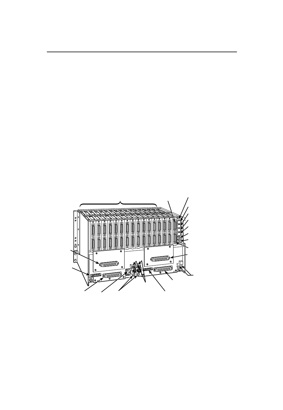
The initial installation procedure for the Model 3551 DSU requires the installation of a
rear connector plate onto the rear of the COMSPHERE 3000 Series Carrier. After the
initial installation, the DSU can be installed or uninstalled by simply removing the DSU
from the carrier.
"
Procedure
1. At the rear of the carrier, set the tab on the rear connector plate into one of the
slotted grooves on the carrier’s backplane. Loosely fasten the screws. Make sure
the rear connector plate uses the same slot position intended for the DSU.
2. Loosely fasten the screw attached to the rear connector plate, allowing for slight
adjustment that may be needed when installing the DSU.
3. Change any default hardware strap settings that may be required before installing
the DSU.
99-16246
SDU Circuit Card
CC In/DC Out
CC Out/DC In
FP In
FP Out
S2-Carrier Address
S1-Protocol Strap
25-Pin V.35 Interface
25-Pin
EIA-232/V.24
Interface
DSUs
Dial Network
Interface Module
(Slots 1 – 8)
Alarm
E1 & E2
DDS Interface
(Slots 1 – 8)
Not Supported
For 3551 DSUs
Power
Connectors
Fuses
AC
Power
DDS Interface
(Slots 9 – 16)
Not
Supported
For 3551
DSUs
Dial
Network
Interface
Module
(Slots
9 – 16)
4. Using a Phillips screwdriver, loosen the screw holding the circuit pack lock and
rotate the lock to the open position. Open the latch.