Analog interface (optional), 8‐bit, 80 msps analog‐to‐digital converter (adc), 8‐bit, 165 msps digital‐to‐analog converter (dac) – Pico Communications E-14 User Manual
Page 13
E‐14 Hardware Reference Manual
www.picocomputing.com
Pico Computing, Inc.
13
Analog Interface (Optional)
The Pico E‐14 also comes equipped with two high‐speed analog converters each capable of 14‐bit
resolution. By default, both analog converters are powered down until the sleep lines are driven low
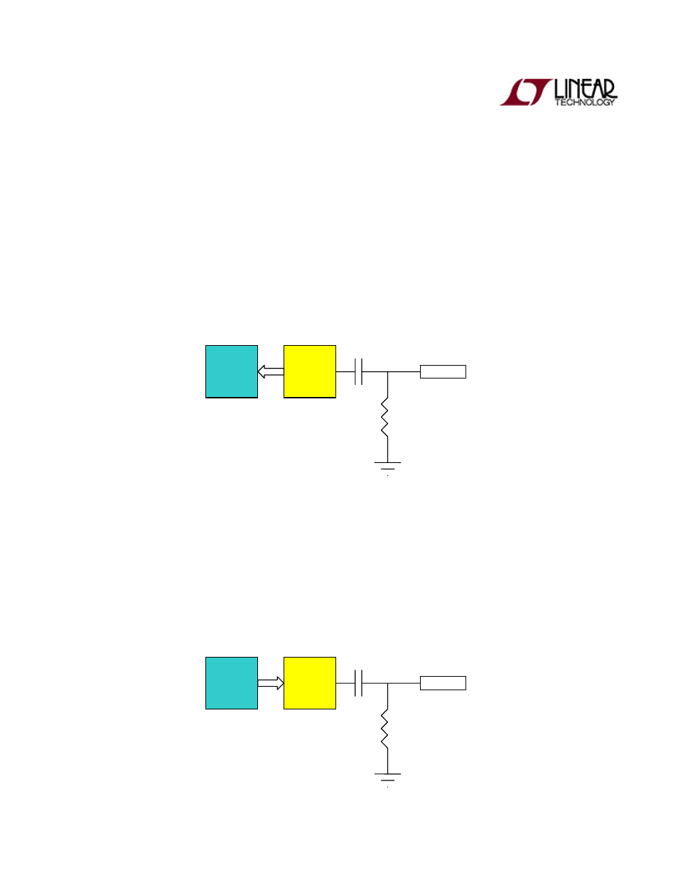
and the amplifier lines are driven high by the FPGA. Both converters are capacitively coupled with pull‐
down resistors on the output to filter out any DC signal components. Both amplifiers are configured
for minimum noise and unity gain.
8‐Bit, 80 MSPS Analog‐to‐Digital Converter (ADC)*
The ADC is configured to utilize the internal 1.0V reference voltage and maximum full scale input,
giving it a 2V pk‐pk input. Currently, the ADC is setup to accept input voltages between 0V and 2V.
Clock modes and input data format is set by the system utilizing configuration pins available to the
FPGA.
8‐Bit, 165 MSPS Digital‐to‐Analog Converter (DAC)*
The DAC is configured to utilize the internal 1.2V reference voltage and maximum full‐scale output,
giving it a 2V pk‐pk output. Since the DAC actually outputs complementary currents, the amplifier is
also utilized as a current to voltage converter and voltage shifter. This allows the voltage to be buffered
within the 0V to 3V rail voltages. Currently, the DAC is setup to output between .5V and 2.5V. This
gives us a comfortable .5V between our maximum outputs and rail voltages. Clock modes and input
data format is set by the system utilizing configuration pins available to the FPGA.
ADC
AMP
Input
DAC
AMP
Output