Typical flash rom allocation table – Pico Communications E-14 User Manual
Page 11
E‐14 Hardware Reference Manual
www.picocomputing.com
Pico Computing, Inc.
11
Flash Memory
The Pico E‐14 comes equipped with at least 64 megabytes of Flash ROM. The Flash ROM is divided into
512 sectors that can be erased independently. Most of the space on the ROM is reserved for the user.
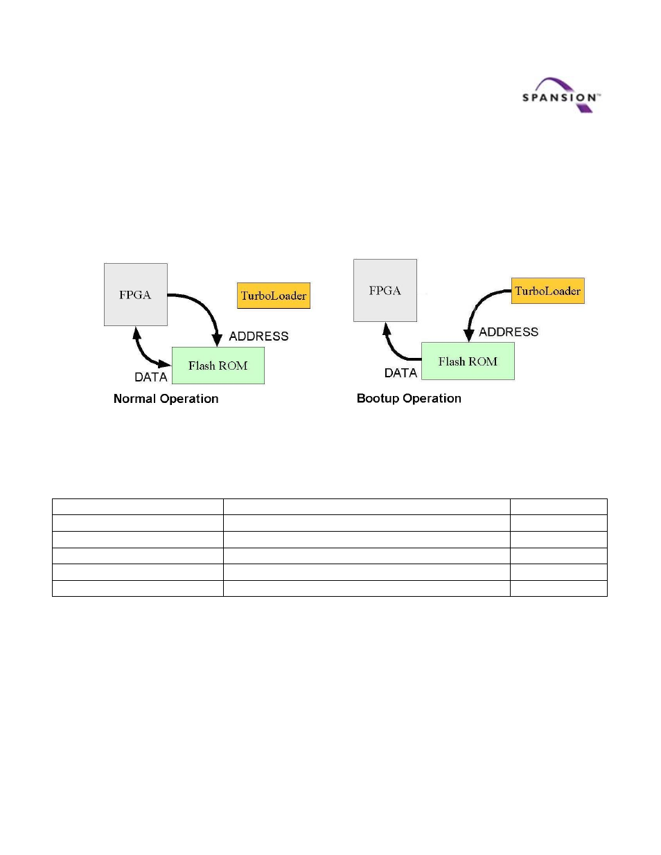
The Flash ROM’s address bus can be controlled by either the TurboLoader or the FPGA, but not both.
During power‐up or reboot, the TurboLoader is in control of the Flash ROM Address bus. At all other
times the FPGA is in control of the address bus.
Figure 2
Typical Flash ROM Allocation Table:
Byte addresses
Description
Flash Sectors
0x00000000‐0x0000FFFF
Tuple Data and configuration management
0
0x00010000‐0x0006FFFF
Primary FPGA Image
1‐6
0x000A0000‐0x000FFFFF
Backup FPGA Image
7‐12
0x000D0000‐0x0012FFFF
Secondary Image including boot loader
13‐19
0x00140000‐0x01FFFFFF
Other FPGA images, executables and data files
20‐511
The Flash ROM has a simple, open file system that allows the user to store FPGA images, ELF binary
files, or other data. The primary image is used to boot the FPGA initially, and the backup image is only
invoked if the primary image fails to load correctly. Executable files are in ELF format and are loaded by
a loader within the secondary image. The primary image can either load the secondary image or pause
for the PC to access and manage the file system.