Troubleshooting & repair, Caution – Lincoln Electric MULTI-SOURCE SVM155-A User Manual
Page 34
TROUBLESHOOTING & REPAIR
F-6
F-6
MULTI-SOURCE
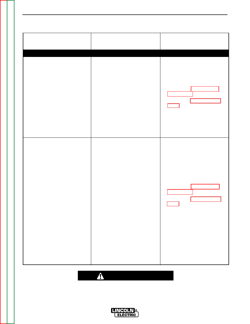
CAUTION
If for any reason you do not understand the test procedures or are unable to perform the test/repairs safely, con-
tact the Lincoln Electric Service Department for electrical troubleshooting assistance before you proceed. Call 1-
800-833-9353.
TROUBLESHOOTING GUIDE
Observe Safety Guidelines
detailed in the beginning of this manual.
OUTPUT PROBLEMS
(SYMPTOMS)
POSSIBLE AREAS OF
MISADJUSTMENT(S)
RECOMMENDED
COURSE OF ACTION
OUTPUT PROBLEMS
The Multi-Source has only
momentary output after the input
contactor activates. Output
returns momentarily approximately
every 75 seconds.
The Multi-Source has momentary
output only. The green light is
OFF and the input contactor
opens.
1. Remove all external welding
cables from the Multi-Source
machine. If the open circuit
voltage (75-80VDC) is present
and constant at the output ter-
minals there may be a short
circuit external to the Multi-
Source. Check the welding
cables and the Multi-Weld
machines.
2. If the problem is not resolved
with the welding cables
removed, there is a fault within
the Multi-Source machine.
1. Check the three phase input
voltage. Make certain it is not
too high for the machine’s rat-
ing and the reconnect panel
configuration.
1. Check all heavy current carry-
ing leads within the Multi-
Source for possible “shorting”
conditions. See the Wiring
Diagram.
1. Check the output filter circuit.
(resistor R9, capacitor C3, and
leads 222C, 292, 294B. See
the Wiring Diagram.
2. Check the voltage feedback
leads 215B and 222A for loose
or faulty connections. See the
Wiring Diagram.