Troubleshooting & repair, Control board removal and replacement (continued) – Lincoln Electric INVERTEC V250-S User Manual
Page 76
F-44
TROUBLESHOOTING & REPAIR
F-44
PROCEDURE
1. Remove input power to the V250-S.
2. Perform
Procedure detailed in Maintenance
Section.
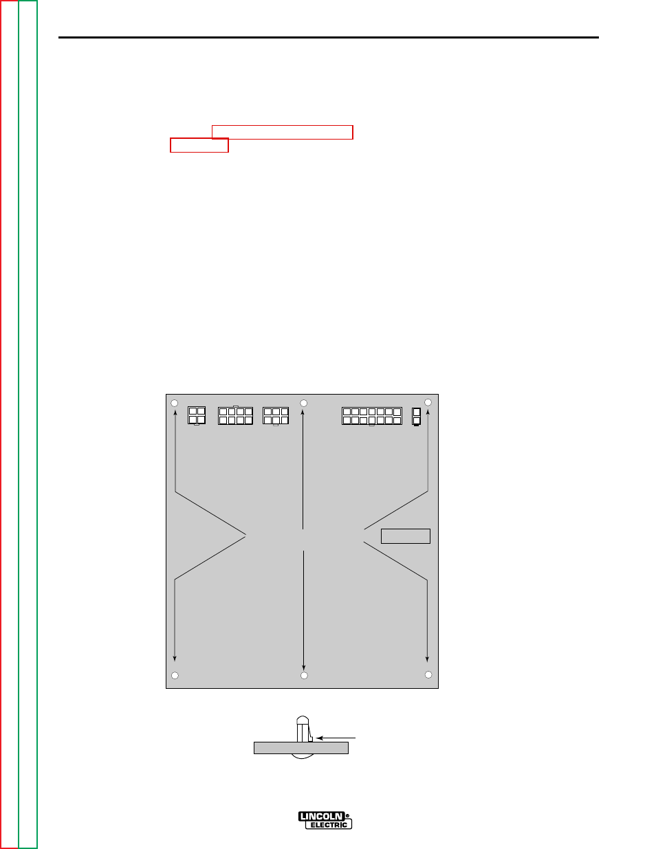
3. Locate the control board and the five
molex type plugs that are connected
to it. See Figure F.13.
4. Carefully remove the five molex type
plugs by depressing the locking tabs
and gently extracting the plugs from
the P.C. board receptacles.
5. Using the needle nose-pliers and
small screwdriver gently remove the
control board from the six mounting
pins by depressing the tabs on the
mounting pins and sliding the board
from the pins. See Figure F.13.
Note: Be sure to observe static elec-
tricity precautions when handling
P.C. boards.
6. When replacing the control board
align the mounting holes with the
mounting pins and gently slide the
P.C. board onto the mounting pins
until the board “snaps” onto the
mounting pins.
Note: Be sure to observe static elec-
tricity precautions when handling
P.C. boards.
7. Replace the five molex type plugs in
their appropriate receptacles.
8. Inspect, clear and secure all leads in
preparation for case wrap-around
reassembly.
9. Using the 5/16” nut-driver replace
the case wrap-around.
CONTROL BOARD REMOVAL AND REPLACEMENT (continued)
INVERTEC V250-S
G2666-[ ]
V250S CONTROL
J1
J2
J5
J3
J4
DEPRESS LOCKING TAB
ON MOUNTING PIN
SIX MOUNTING TABS
Figure F.13
Control Board Plugs and Mounting Pins