Troubleshooting & repair, Power board resistance test (continued) – Lincoln Electric INVERTEC V250-S User Manual
Page 52
F-20
TROUBLESHOOTING & REPAIR
F-20
TEST DESCRIPTION
1. Remove main input power to the
V250 -S.
2. Perform
Procedure detailed in Maintenance
Section.
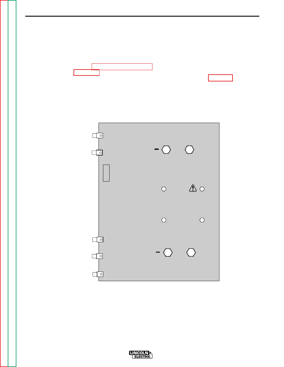
3. Locate the Power Board and associ-
ated lead locations. See Figure F.3.
4. Carefully remove main transformer
primary leads #201, #204, #205 and
#208 from the power board.
5. Use the analog ohmmeter to perform
power board schematic.
POWER BOARD RESISTANCE TEST (continued)
INVERTEC V250-S
V250S POWER G2684
DANGER
HIGH VOLTAGE CAN KILL
204
201
209
208
205
207A
202A
203A
206
+
+
Figure F.3 Power Board Test Points.
See also other documents in the category Lincoln Electric Tools:
- AIR VANTAGE IM10065 (54 pages)
- PRECISION TIG IM936 (44 pages)
- MAGNUM IM887 (20 pages)
- X-Tractor 1GC (4 pages)
- CAN-M393 (3 pages)
- CV ADAPTER IM309-D (46 pages)
- Idealarc 250 (2 pages)
- L12810-1 (4 pages)
- IM359-G (34 pages)
- OUTBACK 145 (34 pages)
- 4.1 (20 pages)
- CV-655 (47 pages)
- K1308-12 (4 pages)
- IM803-B (31 pages)
- LN-25 IM10092 (39 pages)
- PRECISION TIG 275 IM702-A (46 pages)
- Pipeliner 200D (4 pages)
- POWER FEED 10M SINGLE/DUAL SVM172-A (151 pages)
- CLASSIC 300G IM659-B (33 pages)
- INVERTEC V350-PRO IM708 (38 pages)
- Magnum 300 and 400 GMA Gun & Cable Assemblies K514 (29 pages)
- CLASSIC III 10061 (34 pages)
- 347 AC-DC (3 pages)
- INVERTEC IM958 (38 pages)
- Cool-Arc 40 (2 pages)
- IM795 (39 pages)
- Excalibur 11018M MR (1 page)
- METALUX 396T8HO (2 pages)
- MIG PAK HD IM822 (39 pages)
- VINTAGE 400 (CE) IM889-A (49 pages)
- IM481-B (35 pages)
- POWER MIG SVM157-A (91 pages)
- 600-I (2 pages)
- 4R90 (8 pages)
- IM613-B (54 pages)
- pmn (35 pages)
- RANGER 250 IM919 (49 pages)
- Welding Helmet (4 pages)
- IM355-C LN-9F GMA (70 pages)
- IM628 (17 pages)
- COOL ARC 35 IM959 (22 pages)
- POWER MIG 215 (35 pages)
- LN-25 PRO IM901-A (44 pages)
- METALUX 248 (2 pages)
- MAGNUM PCT125 (25 pages)