The tests detailed in, Table f.2, Troubleshooting & repair – Lincoln Electric INVERTEC V250-S User Manual
Page 49: Input rectifier test (continued)
F-17
TROUBLESHOOTING & REPAIR
F-17
6. If the Input Rectifier does not meet
the acceptable readings outlined in
Table F.2. the component may be
faulty. Replace.
Note: Before replacing the Input
Rectifier(D9) check the input
power switch (S1) and perform
the
Test. Also check for leaky or
faulty filter capacitors.
7.
When installing a new Input
Rectifier, torque the mounting nuts to
44IN-LBS. A thin coating of Dow
Corning 340 Heat Sink Compound
(Lincoln E1868) is recommended.
Torque the lead terminals to 31IN-
LBS. See
8. If the Input Rectifier is good be sure
to reconnect leads #207, #207A and
#209 to the correct terminals and
torque to 31IN-LBS. See wiring dia-
gram and Figure F.2.
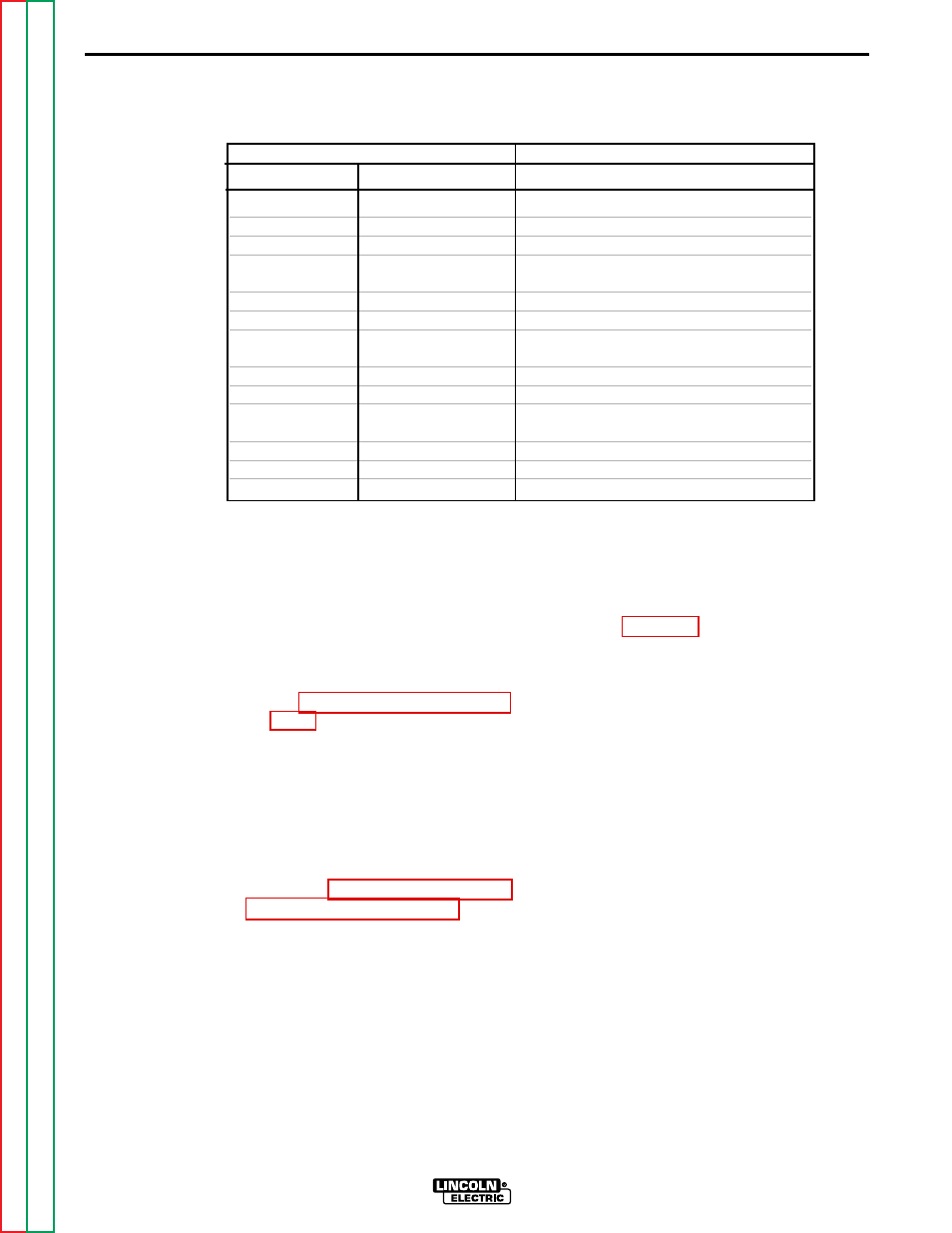
INPUT RECTIFIER TEST (continued)
INVERTEC V250-S
TEST POINT TERMINALS
ANALOG METER X10 RANGE
+ Probe
- Probe
Acceptable Meter Readings
A
207
Greater than 1000 ohms
B
207
Greater than 1000 ohms
C
207
Greater than 1000 ohms
A
209
Less than 100 ohms
B
209
Less than 100 ohms
C
209
Less than 100 ohms
207
A
Less than 100 ohms
207
B
Less than 100 ohms
207
C
Less than 100 ohms
209
A
Greater than 1000 ohms
209
B
Greater than 1000 ohms
209
C
Greater than 1000 ohms
TABLE F.2 Input Rectifier Test Points