The tests outlined in, Table f.3 . see, Troubleshooting & repair – Lincoln Electric INVERTEC V250-S User Manual
Page 53: Power board resistance test (continued)
F-21
TROUBLESHOOTING & REPAIR
F-21
6. If the power board does not meet the
acceptable readings outlined in
Table F.3. the board may be faulty.
Replace. See
Removal and Replacement
Procedure.
Note: Complete power board and filter
capacitor replacement is recommended
.
7. If the power board “passes” the
resistance test proceed to the
Note: Reconnect leads #201, #204,
#205 and #208 to their appropriate ter-
minals.
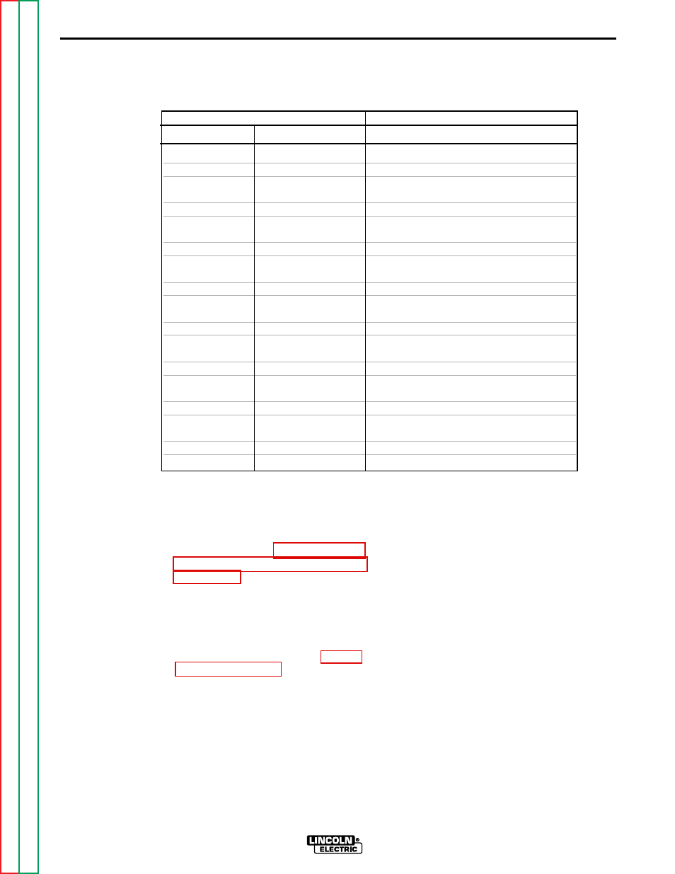
POWER BOARD RESISTANCE TEST (continued)
INVERTEC V250-S
TEST POINT TERMINALS
ANALOG METER X10 RANGE
+ Probe
- Probe
Acceptable Meter Readings
201
207A
Greater than 1000 ohms
207A
201
Less than 100 ohms
204
207A
Greater than 1000 ohms
207A
204
Less than 100 ohms
202A
204
Greater than 1000 ohms
204
202A
Less than 100 ohms
202A
201
Greater than 1000 ohms
201
202A
Less than 100 ohms
205
203A
Greater than 1000 ohms
203A
205
Less than 100 ohms
208
203A
Greater than 1000 ohms
203A
208
Less than 100 ohms
206
208
Greater than 1000 ohms
208
206
Less than 100 ohms
206
205
Greater than 1000 ohms
205
206
Less than 100 ohms
TABLE F.3 Power Board Resistance Test Points.