Lochinvar 000 - 500 User Manual
Page 17
20. Set the thermostat to call for heat. The appliance
is now ready to operate.
Check burner performance by cycling the system while
you observe burner response. Burners should ignite
promptly. Flame pattern should be stable, see
“Main te nance-Normal Flame Pattern.” Turn system
off and allow burners to cool, then cycle burners again
to en sure proper ignition and flame characteristics.
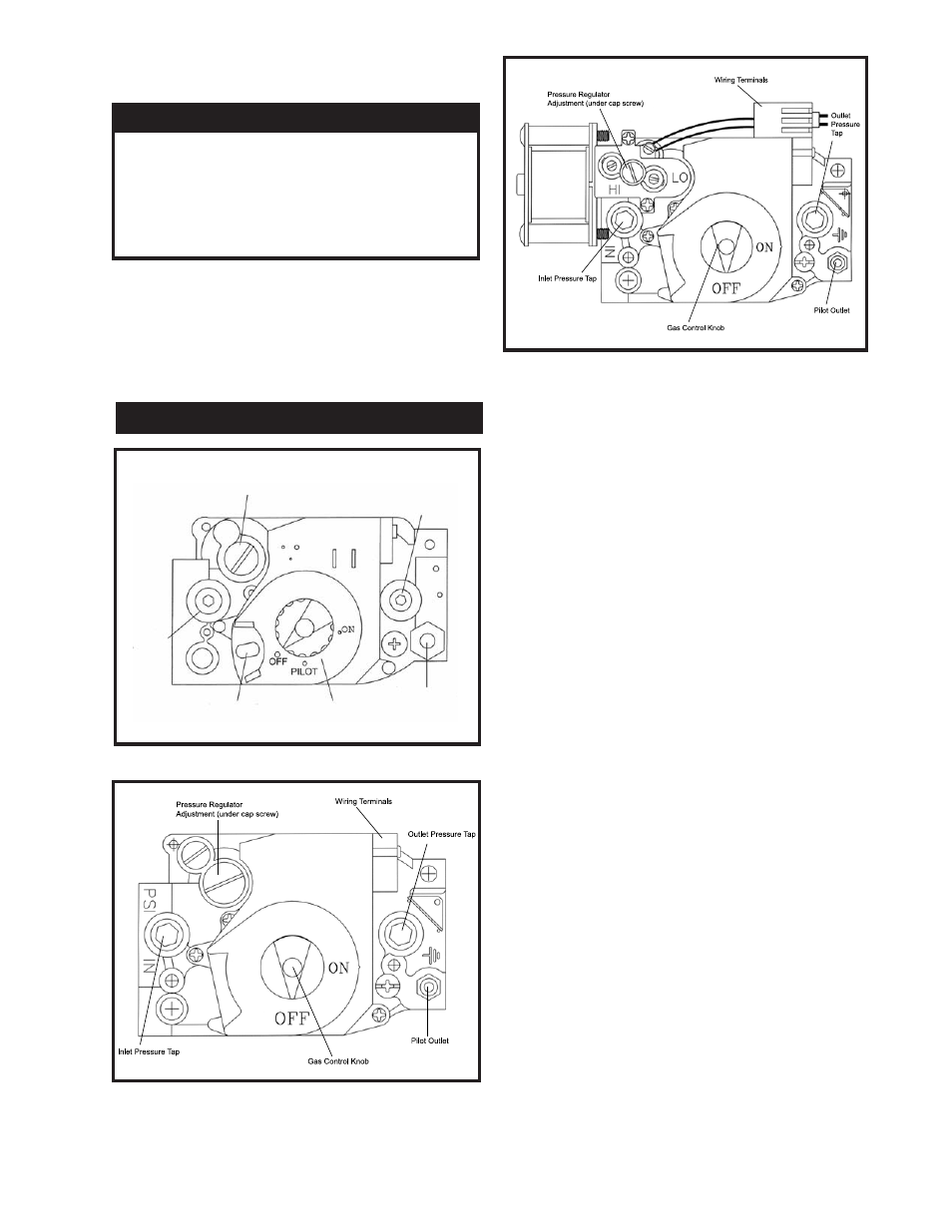
FIG. 20 F1 Gas Valve 90,000 - 270,000 Btu/hr Models
FIG. 21 F9 Gas Valve 90,000 - 500,000 Btu/hr Models
FIG. 22 M9 Gas Valve 45,000 - 399,999 Btu/hr Models
Each unit has a combination gas valve(s) to control the
gas supply to the burners. The 500,000 Btu/hr model
has two combination gas valves to supply gas to the
burners. The com
bi
na
tion valve con
sists of a gas
regulator and two valve seats to meet the requirements
for redundant gas valves. The valve has a gas control
knob that must remain in the open po si tion at all times
when the appliance is in service. Each gas valve has
pres
sure taps located on the inlet and outlet sides.
Manifold pressure is adjusted using the regulator
located on the valve. The manifold pres sure is pre set at
the factory and adjustment is not usu al ly re quired. If
the manifold pressure is to be ad just ed, follow the “Gas
Manifold Pressure Ad just ment Pro ce dure”, page 15 for
proper adjustment.
Venting of Combination Gas Valves
The combination gas valve regulator used on all mod els
is equipped with an integral vent limiting orifice. The
vent limiter ensures that the volume of gas emitted from
the valve does not exceed the maximum safe leak age
rate allowed by agency re quire ments. Com bi na tion gas
valve/regulators equipped with integral vent limiters are
not re quired to have vent or relief lines piped to the
outdoors. A dust cap is provided at the vent termination
point on the valve to prevent block
age of the vent
limiter by foreign material. The com bi na tion gas valve
regulator with an integral vent limiter complies with the
safety code requirements of CSD-1, CF-190(a) as
shipped from the manufacturer with out the in stal la tion
of additional vent lines.
17
Upon completion of any testing on the gas system,
leak test all gas connections with a soap solution
while main burners are operating. Im
me
di
ate
ly
repair any leak found in the gas train or re lat ed
components. Do Not operate an appliance with a
leak in the gas train, valves or related piping.
IMPORTANT
COMBINATION GAS VALVES
Pressure Regulator
Adjustment (under cap screw)
Inlet
Pressure
Tap
Red Reset Button
Gas Control
Knob
Pilot Outlet
Outlet Pressure Tap