Caution, Operator setup (continued), Limit nuts rough adjustment – Linear SLC User Manual
Page 8: Limit nuts fine adjustment
SLR
• SLC • SLD Slide Gate Operator Installation Guide
- 6 -
227968 Revision X19 8-11-2011
Operator Setup (Continued)
Limit Nuts Rough Adjustment
The limit nuts are not preset at the factory and must be
adjusted for the length of the gate in each installation. The
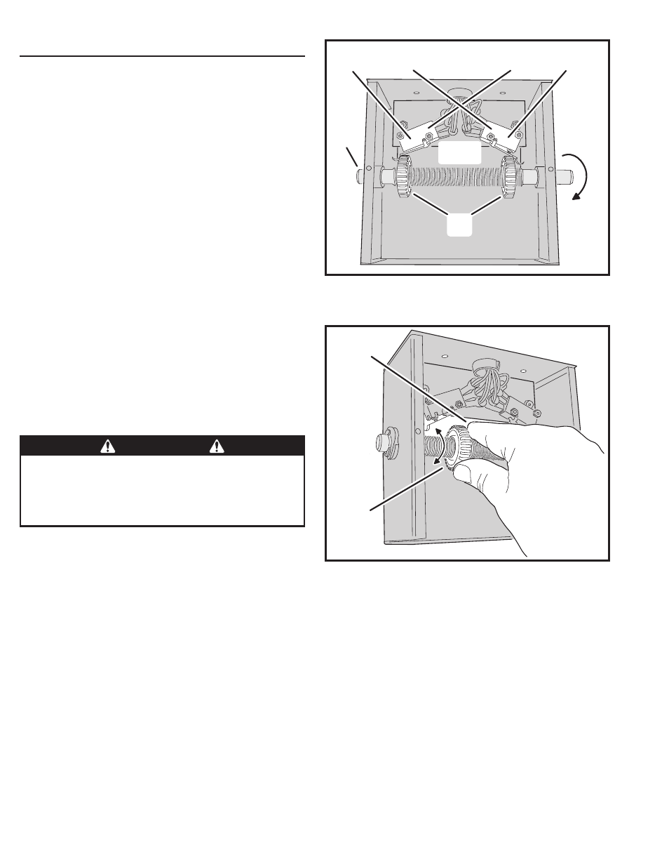
limit switches are activated by two threaded nylon rotary
limit nuts which are attached to a threaded limit shaft driven
by a chain and sprockets from the main drive shaft (see
Figure 8). REMOVE THE CARDBOARD FILLER BEFORE
ADJUSTING THE LIMIT NUTS.
The Controller is factory set for right hand installations. The
left limit nut is for OPEN and the right limit nut is for CLOSE.
The limit nuts fl ip their defi nition in left hand installations.
(see left-right hand programming on Page 11).
1. With the gate connected to the gate operator in a mid-travel position,
the power disconnect switch turned OFF, disconnect the operator
by using the manual disconnect lever, once the operator has been
disconnected, manually move the gate by hand to within a foot of
its fully open position (the foot of distance is necessary to allow for
coasting of the operator after the limit switch is tripped).
2. Once the gate is in this position, adjust the OPEN limit nut until it
activates the limit switch for open. Press down the detent plate and
rotate the nut along the threaded shaft (see Figure 9).
3. After setting the open limit, move the gate to one foot from fully
closed and repeat the process for the CLOSE limit nut (see Figure 9).
Limit Nuts Fine Adjustment
After fi nishing the rough limit nut adjustments, reposition the
gate to approximately the center of travel.
1. Re-engage the operator using the disconnect handle.
2. Turn the power disconnect switch ON.
3. Stand clear of any moving parts and press the OPEN button.
4. After the gate opens, press the CLOSE button.
5. Observe the gate in both directions as it runs through each complete
cycle. Adjust the open or close limit nuts again if necessary. Fine
levels of adjustment can be made by adjusting a few teeth on the
nut at a time. If the gate stops during travel, you may need to adjust
the Open or Close Current Setting or the Maximum Run Timer (see
Pages 12-13).
PRESS DETENT
PLATE DOWN
ROTATE
LIMIT NUT
Figure 9. Setting the Limits
CAUTION
If the operator is installed in a left-hand installation. Set the
Controller to left-hand operation BEFORE running the operator
for the fi ne setting of the limit nuts. Failure to do so will result
in over-shooting the limit switches, and can cause damage to
the operator and/or gate. Refer to programming on Page 11.
LEFT-HAND INSTALLATION
OPEN LIMIT
CLOSE LIMIT
RIGHT-HAND INSTALLATION
OPEN LIMIT
CLOSE LIMIT
RIGHT-HAND
OPEN
DIRECTION
LIMIT
NUTS
LIMIT
SHAFT
LIMIT
SWITCHES
Figure 8. Limit Box Assembly