Warning, Wiring specifi cations, Use copper wire only – Linear SLC User Manual
Page 4: Ac power wiring, Dc control and accessory wiring
SLR
• SLC • SLD Slide Gate Operator Installation Guide
- 2 -
227968 Revision X19 8-11-2011
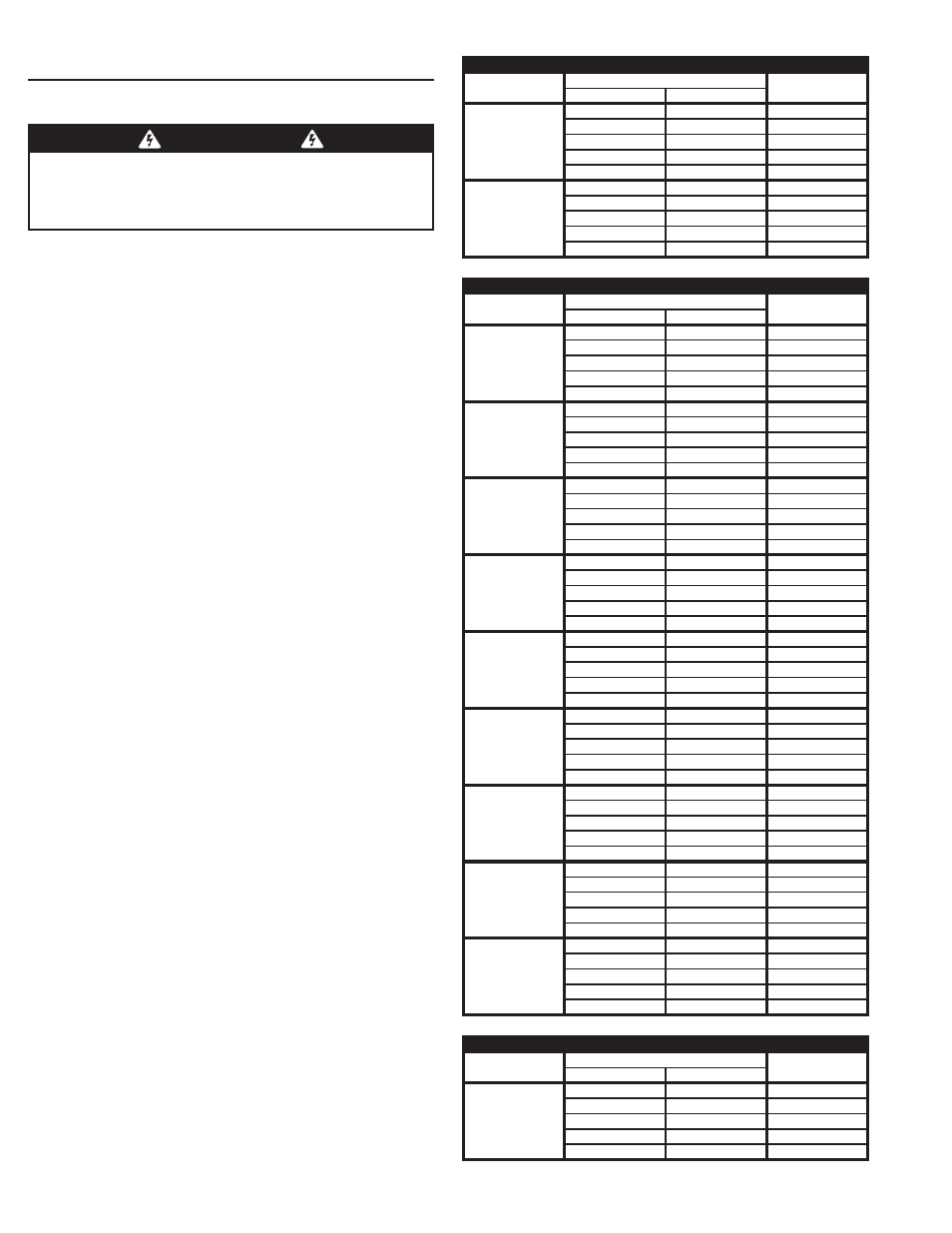
Wiring Specifi cations
Refer to the following steps for details on power and
accessory wiring for the operator.
AC Power Wiring
1. Find the listing on this page corresponding to the model, voltage and
horsepower rating of your operator.
2. The distance shown in the table is measured in feet from the
operator to the power source. DO NOT EXCEED THE MAXIMUM
DISTANCE. These calculations have been based on standard 115 V
and 230 V supplies with a 10% drop allowable. If your supply is under
the standard rating, the runs listed may be longer than what your
application will handle, and you should not run wire too near the
maximum distance for the gauge of wire you are using.
3. When large-gauge wire is used, a separate junction box (not supplied)
may be needed for the operator power connection.
4. Wire length calculations are based on the National Electrical Code,
Article 430 and have been carefully determined based on motor
inrush, brake solenoids, and operator requirements.
5. Connect power in accordance with local codes. The green ground
wire must be properly connected.
6. Wire insulation must be suitable to the application.
7. Electrical outlets are supplied in all 115 VAC models for convenience
with occasional use or low power consumption devices only. If
you choose to run dedicated equipment from these devices, it will
decrease the distance for maximum length and the charts will no
longer be accurate.
DC Control and Accessory Wiring
1. All control devices are now 24 VDC, which can be run up to 2000
feet with 14 AWG wire.
2. Control wiring must be run in a separate conduit from power wiring.
Running them together may cause interference and faulty signals in
some accessories.
3. A three-wire shielded conductor cable is required to connect two
operators together for dual operation. You must use Belden 8760
Twisted Pair Shielded Cable (or equivalent) only – P/N 2500-1982,
per foot). See Page 25 for details of this connection. Note: The shield
wire should be connected in both the operators.
WARNING
ALL AC ELECTRICAL CONNECTIONS TO THE POWER SOURCE AND
THE OPERATOR MUST BE MADE BY A LICENSED ELECTRICIAN
AND MUST OBSERVE ALL NATIONAL AND LOCAL ELECTRICAL
CODES.
USE COPPER WIRE ONLY!
MODEL SLR POWER WIRING
VOLTS & HP
MAXIMUM DISTANCE (FEET)
WIRE GAUGE
SINGLE
DUAL
115 VOLTS
1/2-HP
316
158
12
502
251
10
800
400
8
1272
636
6
2022
1011
4
230 VOLTS
1/2-HP
764
382
12
1218
609
10
1936
968
8
3076
1538
6
4896
2448
4
MODEL SLC POWER WIRING
VOLTS & HP
MAXIMUM DISTANCE (FEET)
WIRE GAUGE
SINGLE
DUAL
115 VOLTS
1/2-HP
222
111
12
354
177
10
566
283
8
900
450
6
1430
715
4
115 VOLTS
3/4-HP
178
89
12
282
141
10
450
255
8
716
358
6
1140
570
4
115 VOLTS
1-HP
160
80
12
254
127
10
406
203
8
646
323
6
1026
513
4
208 VOLTS
1/2-HP
760
380
12
1200
600
10
1924
962
8
3060
1830
6
4864
2432
4
208 VOLTS
3/4-HP
604
302
12
958
478
10
1526
763
8
2424
1212
6
3856
1928
4
208 VOLTS
1-HP
544
272
12
864
432
10
1374
686
8
2184
1092
6
3476
1738
4
230 VOLTS
1/2-HP
894
447
12
1422
711
10
2264
1132
8
3600
1800
6
5724
2862
4
230 VOLTS
3/4-HP
710
355
12
1128
564
10
1796
898
8
2852
1426
6
4538
2269
4
230 VOLTS
1-HP
640
320
12
1016
508
10
1616
808
8
2570
1285
6
4090
2045
4
MODEL SLD POWER WIRING
VOLTS & HP
MAXIMUM DISTANCE (FEET)
WIRE GAUGE
SINGLE
DUAL
115 VOLTS
1/2-HP
430
215
12
684
342
10
1090
545
8
1732
866
6
2756
1378
4