Model slr exploded view – Linear SLC User Manual
Page 31
SLR
• SLC • SLD Slide Gate Operator Installation Guide
- 29 -
227968 Revision X19 8-11-2011
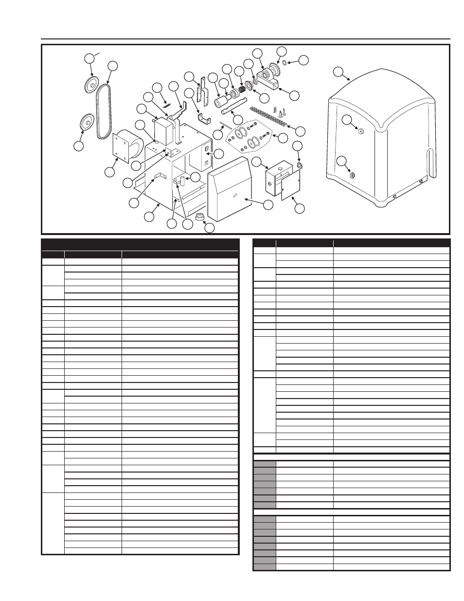
Model SLR Exploded View
1
31
30
29
27
33
32
34
2A
2
3
28
A
24
26
22
25
36
39
15
13
23
4
21
35
20
12
11
10
9
8
16
14
18
19
17
7
7A
28
NOTE: MAY HAVE OPTIONAL TORQUE LIMITER
1A
1B
40
MODEL SLR MECHANICAL PARTS LIST
REF. #
PART #
DESCRIPTION
1
2300-907
Operator Cover
1A
2510-354
Plunger Reset Assembly
2500-2240
Plunger Reset Button
2500-2241
Plunger Extension Only
1B
2200-790
Lock for Cover, with Keys
2200-824
Extra Keys
2
2110-796
Main Frame Assembly
2A
2100-2006
Lock Tab Bracket
3
2100-2055
Bottom Shelf
4
2100-1985
Pillow Block Tube Spacer
7
2200-942
Gear Reducer, 20:1
7A
2100-1980
Gear Reducer Tube Spacer
8
2110-783
Reducer Coupler, with Oilite Bushing
10
2100-2026
Disconnect Collar
11
2200-115
Disconnect Collar Spring
12
2200-014
Shaft Collar, 1” diameter, 3/8” LTB
13
2100-1983
Drive Shaft, 1” diameter
13A
2100-529
1” Woodruff Key
14
2100-1986
Disconnect Handle Fulcrum Bracket
15
2100-549
Pin for Disconnect Handle
2400-169
Push-on Nut, 1/4” (not shown)
16
2120-477
Disconnect Handle
17
2100-2060
Disconnect Fulcrum Bracket
18
2100-2059
Disconnect Lever
19
2200-939
Locking Handle Spring
20
2200-274
Pillow Block Bearing, 1” diameter
21
2200-042
Sprocket, 48-B-15, 1” bore
22
2200-041
Sprocket, 48-B-15, 1/2” bore
23
2200-966
#48 Roller Chain, 15 Links
2200-010
#48 Master Link
24
2500-2393
APeX Module
2100-2104
APeX Mounting Plate
2300-1025
Controller Plastic Cover Only
2510-423
Knob Kit
25
2520-396-SLC
Limit Box Assembly with Cover
2100-057
Limit Shaft
2200-029
Oilite Bushing
2200-030
Limit Nut
2200-193
1/2” E-ring
2300-946
Heyco Bushing with Wire Guards
2500-440
Limit Switch
2100-261
Detent Plate
2200-028
Detent Spring
REF. #
PART #
DESCRIPTION
26
2300-945
Limit Box Cover
27
2510-274
Motor Assembly, 115 VAC, with Harness
2510-275
Motor Assembly, 230 VAC, with Harness
28
2500-261
Capacitor for 115 VAC
2500-552
Capacitor for 230 VAC
28A
2100-872
Capacitor Clamp
29
2200-647
4” Pulley, 1/2” bore
30
2200-118
4” Pulley, 5/8” bore
31
2200-013
V-belt, 4L 31”
32
2500-2435
Alarm
33
2100-2114
Stop/Reset Button Bracket
34
2500-1495
Stop/Reset Button
35
2200-650
Sprocket, 41-B-24, 1” bore
36
2110-823
Idler Assembly
2300-697
Idler Wheel, UHMW
2400-527
1/2” Shoulder Bolt
2400-528
1/2” Lock Washer
2400-529
1/2” Nut
37
2100-2109
APeX Controller Mounting Bracket (not shown)
38
2510-422
115 VAC Power Box Assembly
2510-430
230 VAC Power Box Assembly
2500-2411
Power Switch
2500-2413
Power Outlet (only available on 115 VAC Models)
2500-212
115 VAC - 24 VAC Power Transformer
2500-791
230 VAC - 24 VAC Power Transformer
2100-2113
Back Plate
2100-2112
Cover Plate
39
2510-424
115 VAC Wiring Harness Assembly (not shown)
2510-428
230 VAC Wiring Harness Assembly (not shown)
40
2400-501
1” Rotor Clip
PARTS FROM ACCESSORY BOX (Not shown in exploded view)
2100-2007
Gate Attachment Bracket
2400-170
U-bolt, 3”
2100-054
#41 Chain Tension Bolt
2200-367
Chain Spring
2200-027
#41 Master Link
2200-150
#41 Chain, per Foot
2400-152
Square Head Bolt, 3/8”
OPTIONAL PARTS
2100-2010
Base Plate for Operator
2100-2008
Critter Plate
2650-107
Remote Disconnect Kit
2120-483
Post Mounting Kit
2220-045
2” Torque Limiter Assembly Complete
2300-693
Friction Disc (Pair)
2200-676
4” Pulley for Torque Limiter
2200-877
Bushing for Pulley