Dual gate installations – Linear SLC User Manual
Page 27
SLR
• SLC • SLD Slide Gate Operator Installation Guide
- 25 -
227968 Revision X19 8-11-2011
Dual Gate Installations
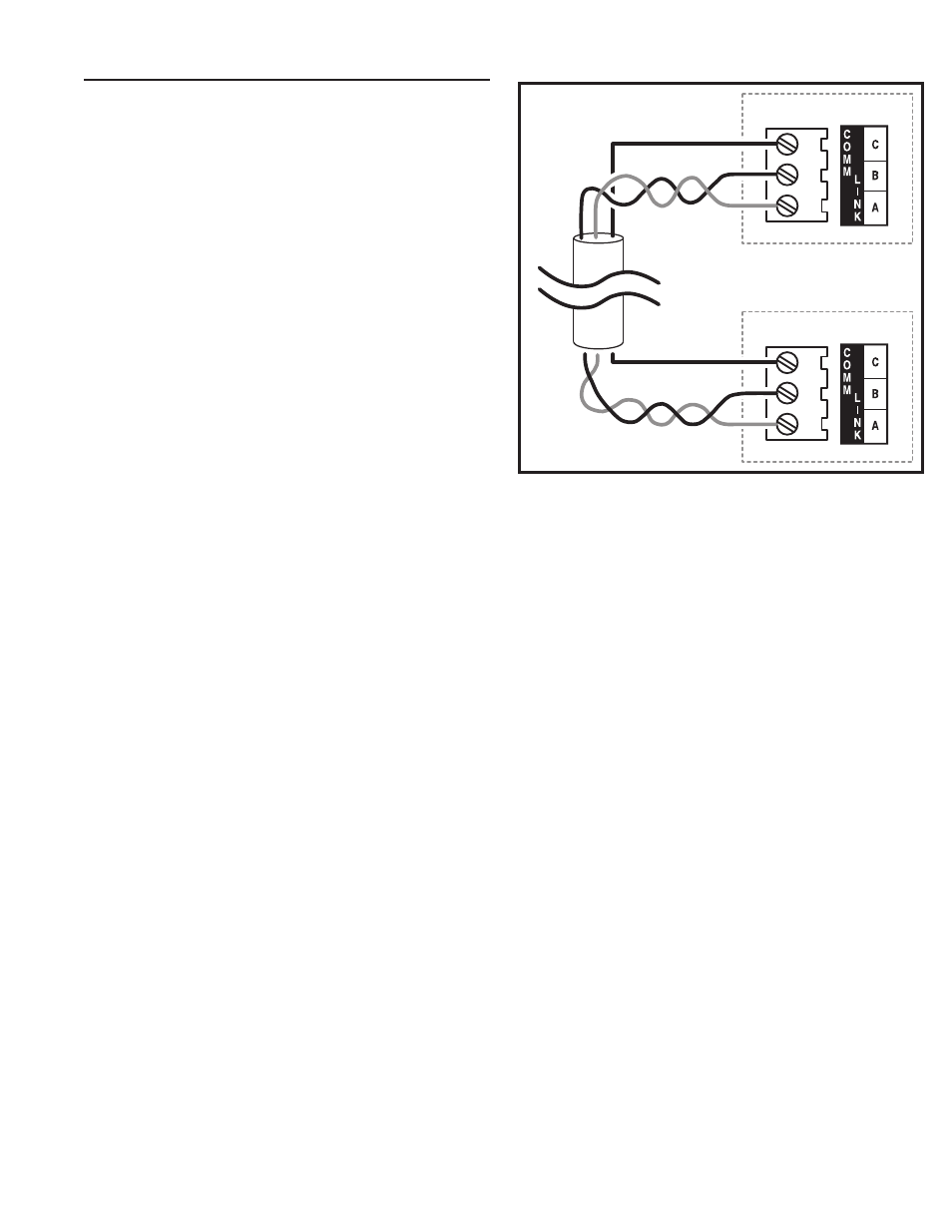
Two operators can be used in dual gate installations. The operators
communicate with each other through the 3-wire COMM LINK terminals.
When one operator activates, the COMM LINK connection signals
the other operator to activate. Each operator functions independently,
controlling its gate and monitoring its inputs and accessories.
A three-wire shielded conductor cable is required to connect two
operators together for dual operation. Use Belden 8760 Twisted Pair
Shielded Cable (or equivalent) only – P/N 2500-1982, per foot).
✓ NOTE: The shield wire should be connected COMM LINK terminal
“C” in both operators.
Three of the programming functions available are only used for dual gate
installations:
• Dual Gate Enable
Dual Gate Enable must be set for all dual gate installations.
• Stagger Mode
The Stagger Mode function determines if the operator has a delayed
open or a delayed close. In dual swing gate installations, typically one
operator is programmed for delayed open, and the other operator is
programmed for delayed close.
• Stagger Delay Time
The Stagger Time sets the length of the delay for the Stagger Mode.
See Pages 11, 13, & 14 for details on these three dual gate programming
functions.
Set the following parameters in each gate operator individually in a single gate
mode before connecting the network cable and operating in dual gate mode.
1. Open and Close Limit settings
2. Open and Closed direction inherent
entrapment protection (OC & CC)
After these parameters have been set, and each operator has been
tested independently and is functioning correctly in single gate mode,
then set BOTH operators to dual gate (dg) in the Paired Mode setup step
under Basic Programming steps.
OPERATOR #1
OPERATOR #2
USE BELDEN 8760 TWISTED PAIR
SHIELDED CABLE OR EQUIVALENT
SHIELD
CONNECT SHIELD
WIRE AT BOTH ENDS
DUAL GATE
COMM LINK
WIRING
CONNECT
C - C
B - B
A - A
SHIELD
Figure 12. COMM LINK Wiring