General, Venting – Lochinvar Knight Wall Mount Soiler 51-211 User Manual
Page 19
19
3
General
venting
(continued)
Installation & Operation Manual
Installing vent and air piping
Use only cleaners, primers, and solvents
that are approved for the materials which
are joined together.
NOTICE
1. Work from the boiler to vent or air termination. Do not
exceed the lengths given in this manual for the air or vent
piping.
2. Cut pipe to the required lengths and deburr the inside
and outside of the pipe ends.
3. Chamfer outside of each pipe end to ensure even
cement distribution when joining.
4. Clean all pipe ends and fittings using a clean dry rag.
(Moisture will retard curing and dirt or grease will prevent
adhesion.)
5. Dry fit vent or air piping to ensure proper fit up before
assembling any joint. The pipe should go a third to
two-thirds into the fitting to ensure proper sealing after
cement is applied.
6. Priming
and
Cementing:
a. Handle fittings and pipes carefully to prevent
contamination
of
surfaces.
b. Apply a liberal even coat of primer to the fitting
socket and to the pipe end to approximately 1/2"
beyond the socket depth.
c. Apply a second primer coat to the fitting socket.
d. While primer is still wet, apply an even coat of
approved cement to the pipe equal to the depth of
the fitting socket along with an even coat of
approved cement to the fitting socket.
e. Apply a second coat of cement to the pipe.
f.
While the cement is still wet, insert the pipe into
the fitting, if possible twist the pipe a 1/4 turn as
you insert it. NOTE: If voids are present,
sufficient cement was not applied and joint could
be
defective.
g.
Wipe excess cement from the joint removing ring or
beads as it will needlessly soften the pipe.
PVC/CPVC
Table 3D PVC/CPVC Vent Pipe, and Fittings
All PVC vent pipes must be glued, properly
supported, and the exhaust must be
pitched a minimum of a 1/4 inch per foot
back to the boiler (to allow drainage of
condensate).
NOTICE
ƽ WARNING The vent connection to the appliance must
be made with the starter piece provided
with the appliance if PVC/CPVC vent is to
be used. The field provided vent fittings
must be cemented to the CPVC pipe section
using an “All Purpose Cement” suitable for
PVC and CPVC pipe. Use only the vent
materials, primer, and cement specified in
Table 3D to make the vent connections.
Failure to follow this warning could result
in fire, personal injury, or death.
ƽ WARNING
Insulation should not be used on PVC
or CPVC venting materials. The use of
insulation will cause increased vent wall
temperatures, which could result in vent
pipe failure.
Approved PVC/CPVC Vent Pipe and Fittings
Item
Material
Standard
Vent pipe
PVC Schedule 40, 80 ANSI/ASTM D1785
PVC - DWV
ANSI/ASTM D2665
CPVC Schedule 40, 80 ANSI/ASTM F441
Vent fittings
PVC Schedule 40
ANSI/ASTM D2466
PVC Schedule 80
ANSI/ASTM D2467
CPVC Schedule 80
ANSI/ASTM F439
Pipe Cement /
Primer
PVC
ANSI/ASTM D2564
CPVC
ANSI/ASTM F493
NOTICE: DO NOT USE CELLULAR (FOAM) CORE PIPE
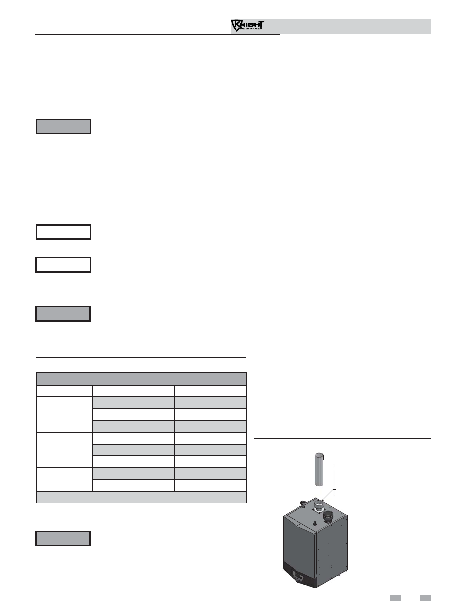
Figure 3-7 Near Boiler PVC/CPVC Venting
This product has been approved for use with the PVC/CPVC
vent materials listed in Table 3D.
NOTE: In Canada, CPVC and PVC vent pipe, fi ttings and cement/
primer must be ULC-S636 certifi ed.
CPVC STARTER PIECE
For models 51 - 106 when transitioning from 2
to 3 inch vent diameter, a 2" pipe section and
2"to 3" increaser are required to be CPVC when
PVC/CPVC vent is used.
For installations using 2" vent, the first seven
(7) equivalent feet of vent must be CPVC (field
supplied). See examples on this page.
ƽ WARNING
Examples: 1. Seven (7) feet vertical
2. Connector + 90° elbow + 2 feet horizontal
3. One (1) foot vertical + 90° elbow + 1 foot
horizontal