Operation – Lincoln Electric POWER FEED SVM185-A User Manual
Page 54
OPERATION
B-36
B-36
POWER FEED® 25M
WELD:
After upslope, the power source output and the wire
feed speed continue at the weld settings.
CRATER:
As soon as the trigger is released, the wire feed speed
and power source output ramp to the crater settings
throughout the crater time. The time period of ramping
from the weld settings to the crater settings is called
DOWNSLOPE.
BURNBACK:
After the crater time expires, the wire feed speed is
turned OFF and the machine output continues for the
burnback time.
POSTFLOW:
Next, the machine output is turned OFF and shielding
gas continues until the post flow timer expires.
Shielding
Gas
Idle
Preflow
Strike
Upslope
Weld
Burnback
Postflow
Idle
WFS
On
Off
Run-in
Off
Weld
Off
Weld
Ar
c
Es
ta
bl
ish
ed
Tr
ig
ge
r P
ul
le
d
Tr
ig
ge
r R
el
ea
se
d
2 Step Trigger
Start = ON
Crater = ON
Burnback = ON
1.5 sec max.
Start
Start time
B urnback Time
Downslope
Crater
Crater ti me
Power
Source
Output
Crater
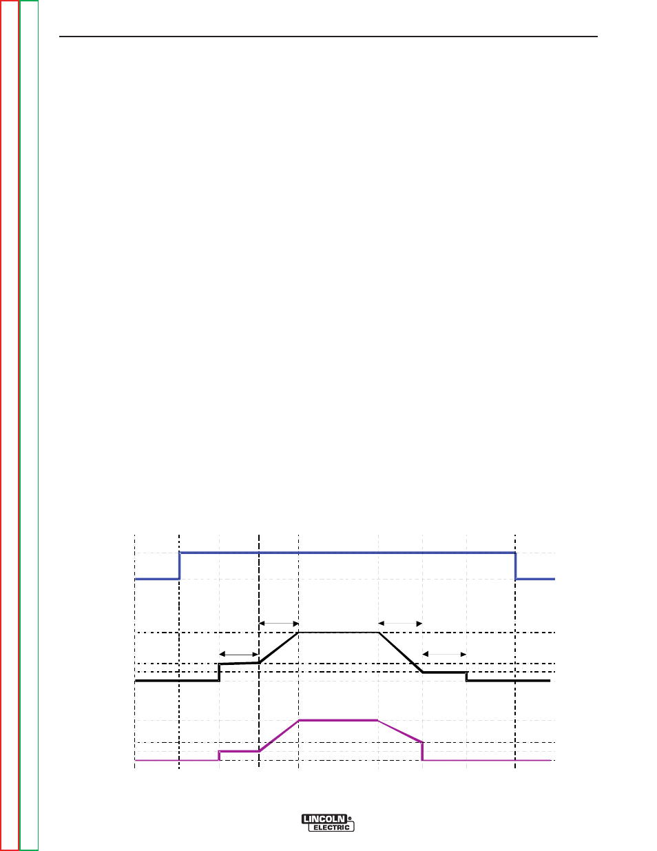
FIGURE B.21
EXAMPLE 3 - 2 STEP TRIGGER:
Customized Arc
Start, Crater and Arc End. Sometimes it is advanta-
geous to set specific arc start, crater and arc ending
parameters for the ideal weld. Many times when weld-
ing aluminum crater control is necessary to make a
good weld. This is done by setting Start, Crater and
Burnback functions to desired values. (See Figure
B.21)
For this sequence,
PREFLOW:
Shielding gas begins to flow immediately when the gun
trigger is pulled.
STRIKE:
After preflow time expires, the power source regulates
to the start output and wire is advanced towards the
work piece at the Strike WFS. If an arc is not estab-
lished within 1.5 seconds, the power source output and
wire feed speed skips to the weld settings.
UPSLOPE:
Once the wire touches the work and an arc is estab-
lished, both the machine output and the wire feed
speed ramp to the weld settings throughout the start
time. The time period of ramping from the start settings
to the weld settings is called UPSLOPE.