Kenwood XD-9581MD User Manual
Page 7
XD-9581MD (En)
7
Preparation section
Basic
section
Application section
Knowledge sections
Before applying power
− +
3
3
OPTICAL
DIGITAL
OUTPUT
OPTICAL
1
OPTICAL
2
System connection
1. Be sure to insert all connection cords securely. If their
connections are imperfect, the sound may not produced or
noise may interfere.
2. Before plugging or unplugging a connection cord, be sure to
unplug the power cord from the wall AC outlet, if connection
cords are plugged or unplugged with the power cord left
plugged in, malfunction or damage may result.
1.When arranging the system units in a vertical, stacked
configuration, observe the stacking order indicated in the
system connection diagram.
2. In case an associated system component is connected, also
read the instruction manual of the component.
3. Align the front panels of the unit flush.
4. Never short-circuit the + and – speaker cords.
5. If the left and right speaker connections or the + and – polarity
are inverted, the sound will be unnatural with unclear position-
ing of musical instruments, etc. Be sure to connect them
without mistake.
Notes
Notes
Twist
1
4
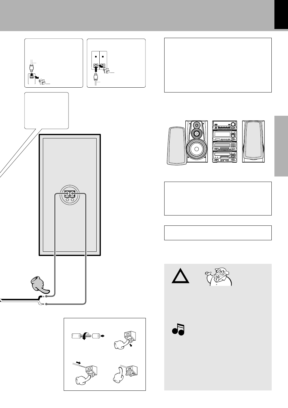
To maintain proper ventilation, be sure to leave a space
around the unit (from the largest outer dimensions in-
cluding projections) equal to, or greater than, shown
below.
Top panel : 50 cm, Rear panel : 10 cm, Left and right panel
: 10 cm
Caution regarding placement (Front view)
Note on connection of optical-fiber cable
÷Insert the optical-fiber cable straight into the connector until
it clicks.
÷Be sure to attach the protection cap when the connector is
not used.
÷Never bend or bundle the optical-fiber cable.
÷All of the optical-fiber cables sold in audio stores cannot
always be used.
÷If the cable you purchased cannot be connected to this unit,
please consult your dealer or KENWOOD distributor.
Caution
Caution
3
Speaker (left)
Speaker Section
Speaker cord
Connect correctly + to + and - to -.
2
Always execute
the connection be-
tween DP-MH5 and
DM-H5 at this posi-
tion.
Digital input terminal
Optical fiber cable
Remove cap
Remove the protection
cap for use.
(Take care not to lose
the cap.)
Digital output terminal
Remove the protection cap for use.
(Take care not to lose the cap.)
Optical fiber cable
Remove cap
Please install as shown, as otherwise fire may be caused
by overheating.