5. installing the optional interface board – Star Micronics SP300 User Manual
Page 17
– 13 –
2-5. Installing the Optional Interface Board
When using the optional 20 mA current loop interface or the RS-422A interface,
the optional interface board must be mounted to the printer’s main logic board.
The following is the method of mounting the interface board to the printer’s main
logic board.
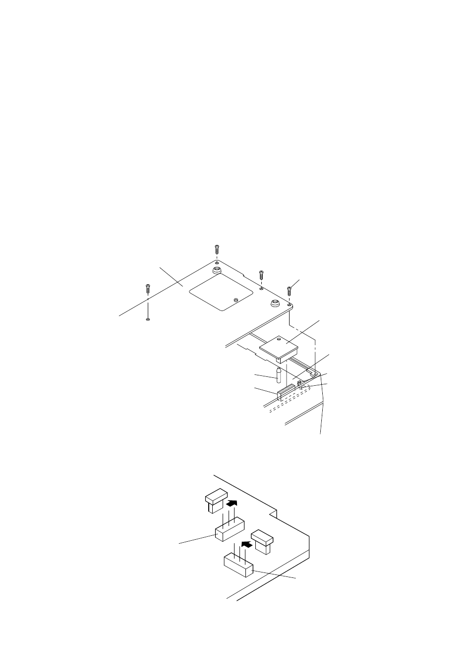
1 Remove the 6 screws on the bottom cover of the printer, then remove the
bottom cover.
2 Connect the optional interface board connector to connector CN9 on the
printer’s main logic board.
3 At the same time, insert the plastic board support of the main logic board into
the hole on the interface board.
4 Switch SW5 and SW6 on the main logic board from A-C to B-C.
5 Mount the bottom cover to the printer and fasten the 6 screws to fix it in place
on the printer.
Fig. 2-6 Installing the optional interface board
Fig. 2-7 Switch SW5 and SW6
Bottom cover
Screw
Optional interface board
Main logic board
SW5
SW6
Board support
CN9
A
C
B
A
C
B
SW5
SW6