Register descriptions, Si5351a/b/c – Silicon Laboratories SI5351A/B/C User Manual
Page 25
Si5351A/B/C
Preliminary Rev. 0.95
25
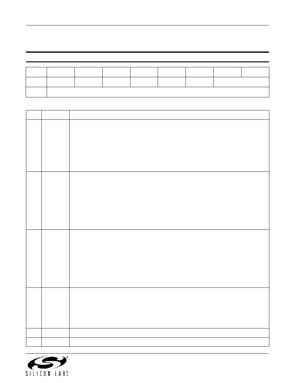
8. Register Descriptions
Reset value = 0000 0000
Register 0. Device Status
Bit
D7
D6
D5
D4
D3
D2
D1
D0
Name
SYS_INIT
LOL_B
LOL_A
LOS
REVID[1:0]
Type
R
R
R
R
R
R
R
Bit
Name
Function
7
SYS_INIT
System Initialization Status.
During power up the device copies the content of the NVM into RAM and performs a system
initialization. The device is not operational until initialization is complete. It is not recom-
mended to read or write registers in RAM through the I
2
C interface until initialization is com-
plete. An interrupt will be triggered (INTR pin = 0, Si5351C only) during the system
initialization period.
0: System initialization is complete. Device is ready.
1: Device is in system initialization mode.
6
LOL_B
PLLB Loss Of Lock Status.
Si5351A/C only. PLLB will operate in a locked state when it has a valid reference from CLKIN
or XTAL. A loss of lock will occur if the frequency of the reference clock forces the PLL to
operate outside of its lock range as specified in Table 3, or if the reference clock fails to meet
the minimum requirements of a valid input signal as specified in Table 4. An interrupt will be
triggered (INTR pin = 0, Si5351C) during a LOL condition.
0: PLL B is locked.
1: PLL B is unlocked. When the device is in this state it will trigger an interrupt causing the
INTR pin to go low (Si5351C only).
5
LOL_A
PLL A Loss Of Lock Status.
PLL A will operate in a locked state when it has a valid reference from CLKIN or XTAL. A loss
of lock will occur if the frequency of the reference clock forces the PLL to operate outside of
its lock range as specified in Table 3, or if the reference clock fails to meet the minimum
requirements of a valid input signal as specified in Table 4. An interrupt will be triggered
(INTR pin = 0, Si5351C only) during a LOL condition.
0: PLL A is operating normally.
1: PLL A is unlocked. When the device is in this state it will trigger an interrupt causing the
INTR pin to go low (Si5351C only).
4
LOS
CLKIN Loss Of Signal (Si5351C Only).
A loss of signal status indicates if the reference clock fails to meet the minimum requirements
of a valid input signal as specified in Table 4. An interrupt will be triggered (INTR pin = 0,
Si5351C only) during a LOS condition.
0: Valid clock signal at the CLKIN pin.
1: Loss of signal detected at the CLKIN pin.
3:2
Reserved
Leave as default.
1:0
REVID[1:0] Revision ID. Device revision number. Set at the factory.