Wiring diagram for alarm output – Sony Security Camera User Manual
Page 28
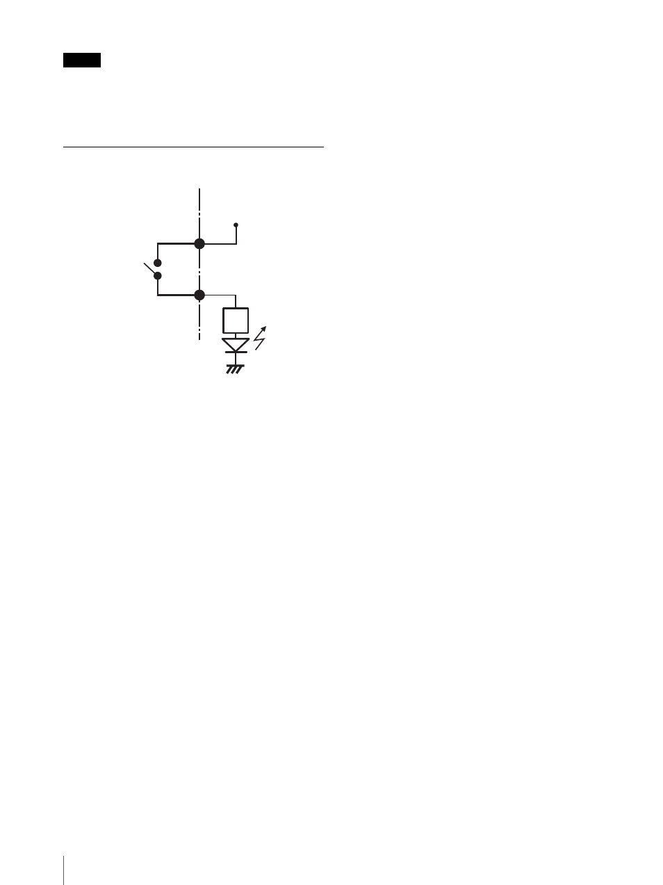
I/O Port
28
Note
When the wiring diagram 2 is used, the NSR is not
electrically isolated, so be sure to construct external
circuits that will not produce noise, excess voltage, or
overcurrents.
Wiring Diagram for Alarm Output
3, 5, 7, 9, 11, 13,
15, 17pin
(ALARM OUT+)
2, 4, 6, 8, 10, 12,
14, 16pin
(ALARM OUT-)
Magnet relay
24 V AC/24 V DC,
1 A or less
Inside of this unit
Outside
5 V
Circuit example
GND
See also other documents in the category Sony Video surveillance systems:
- DH180 (128 pages)
- SNC-DF80N/DF80P (2 pages)
- FCB-EX1010P (52 pages)
- SNC-xx (28 pages)
- SNC-CS50P (16 pages)
- SNC-CS50N (87 pages)
- IPELA NSR Series (186 pages)
- SNC-CS3P (52 pages)
- EM100 (1 page)
- IPELA EXWAREPRO SNC-DM160 (2 pages)
- NTSC/PAL (44 pages)
- IPELA SNC-DH140/DH240 (2 pages)
- IPELA SNC-RZ25P (81 pages)
- FCB-EX1020 (67 pages)
- SNC-DH210 (97 pages)
- EXWAVEPRO SNC-CM120 (2 pages)
- SSC-MD33V (2 pages)
- CV-M300 (2 pages)
- SNC-DF Series (6 pages)
- DF70P (67 pages)
- IPELA SNC CH140 (2 pages)
- SSC-CD53V (2 pages)
- IPELA SNC-P1 (80 pages)
- SSC-MD53V (4 pages)
- CCTV Systems (75 pages)
- SNC-CM120 (2 pages)
- SNC-RZ25P (87 pages)
- FCB-EX980P (61 pages)
- SIR-4150 (20 pages)
- Network Video Monitoring (48 pages)
- SNC-DS10 (8 pages)
- IPELS SNT-EP154 (1 page)
- SSC-CD43VP (6 pages)
- SIR4260V (19 pages)
- SNC-P5 (79 pages)
- SNC-DM160 (2 pages)
- EVI-D100 (48 pages)
- IPELA SNC-DH180 (2 pages)
- SNC-DS60 (100 pages)
- SCC-C7435 (5 pages)
- EVI-D100P (2 pages)
- SNC-VL10P (32 pages)
- IPELA SNC-RS46N (120 pages)
- CD-9255 (8 pages)