13 overheat led (oh), Reset, Nic2 led – SUPER MICRO Computer SUPERSERVER 6012L-6 User Manual
Page 47: Power fail led, Nic1 led, Chapter 5: advanced motherboard setup
Chapter 5: Advanced Motherboard Setup
5-13
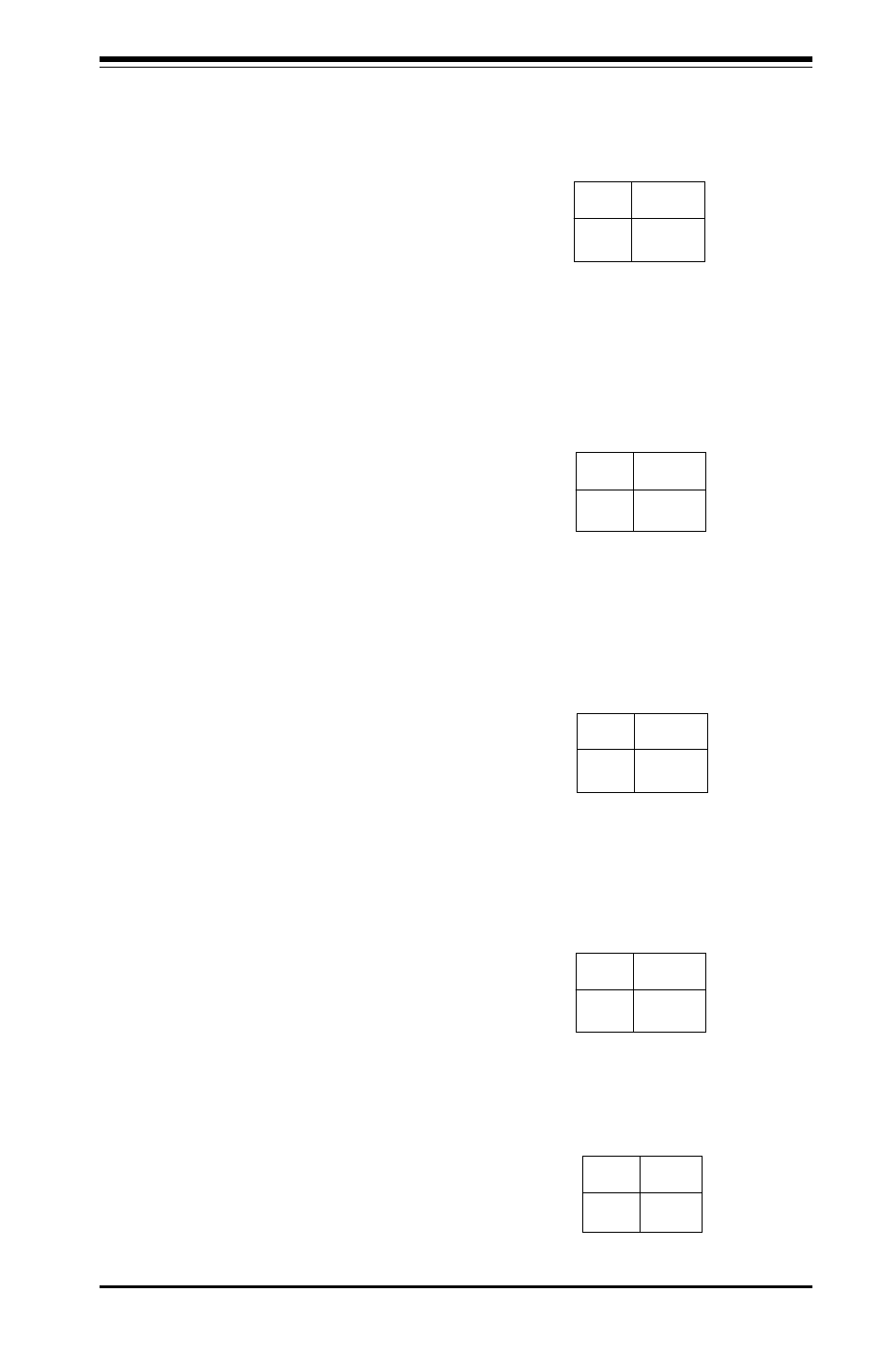
Overheat LED (OH)
Connect an LED to the OH connec-
tion on pins 7 and 8 of JF1 to pro-
vide advanced warning of chassis
overheating. Refer to the table on
the right for pin definitions.
Reset
The Reset connection is located
on pins 3 and 4 of JF1. Attach it
to the hardware reset switch on
the computer case. Refer to the
table on the right for pin defini-
tions.
P in
N u m b e r
3
4
D e fin itio n
R e se t
G ro u n d
R e s e t P in
D e fin itio n s
(J F 1 )
NIC2 LED
The NIC2 (Network Interface Con-
troller for LAN2) LED connection is
located on pins 9 and 10 of JF1.
Attach the NIC2 LED cable to dis-
play network activity. Refer to the
table on the right for pin defini-
tions.
N IC 2 L E D P in
D e fin itio n s
(J F 1 )
P in
N u m b e r
9
1 0
D e fin itio n
+ 5 V
G N D
O ve rh e a t (O H ) L E D
P in D e fin itio n s
(J F 1 )
P in
N u m b e r
7
8
D e fin itio n
+ 5 V
G N D
Power Fail LED
The Power Fail LED connection is
located on pins 5 and 6 of JF1.
Refer to the table on the right for
pin definitions.
P o w e r F a il L E D P in
D e fin itio n s
(J F 1 )
P in
N u m b e r
5
6
D e fin itio n
C o n tro l
G N D
NIC1 LED
The NIC1 (Network Interface Con-
troller for LAN1) LED connection is
located on pins 11 and 12 of JF1.
Attach the NIC1 LED cable to dis-
play network activity. Refer to the
table on the right for pin defini-
tions.
N IC 1 L E D P in
D e fin itio n s
(J F 1 )
P in
N u m b e r
1 1
1 2
D e fin itio n
+ 5 V
G N D