8 connector definitions, 12 s, Power led – SUPER MICRO Computer SUPERSERVER 6012L-6 User Manual
Page 46: Hdd led, Atx power connection, Pwr_sec connection
5-12
S
UPERSERVER 6012L-6 User’s Manual
5-8
Connector Definitions
Power LED
The Power LED connection is lo-
cated on pins 15 and 16 of JF1.
Refer to the table on the right for
pin definitions.
P in
N u m b e r
1 5
1 6
D e fin itio n
+ 5 V
C o n tro l
P W R _ L E D P in D e fin itio n s
(J F 1 )
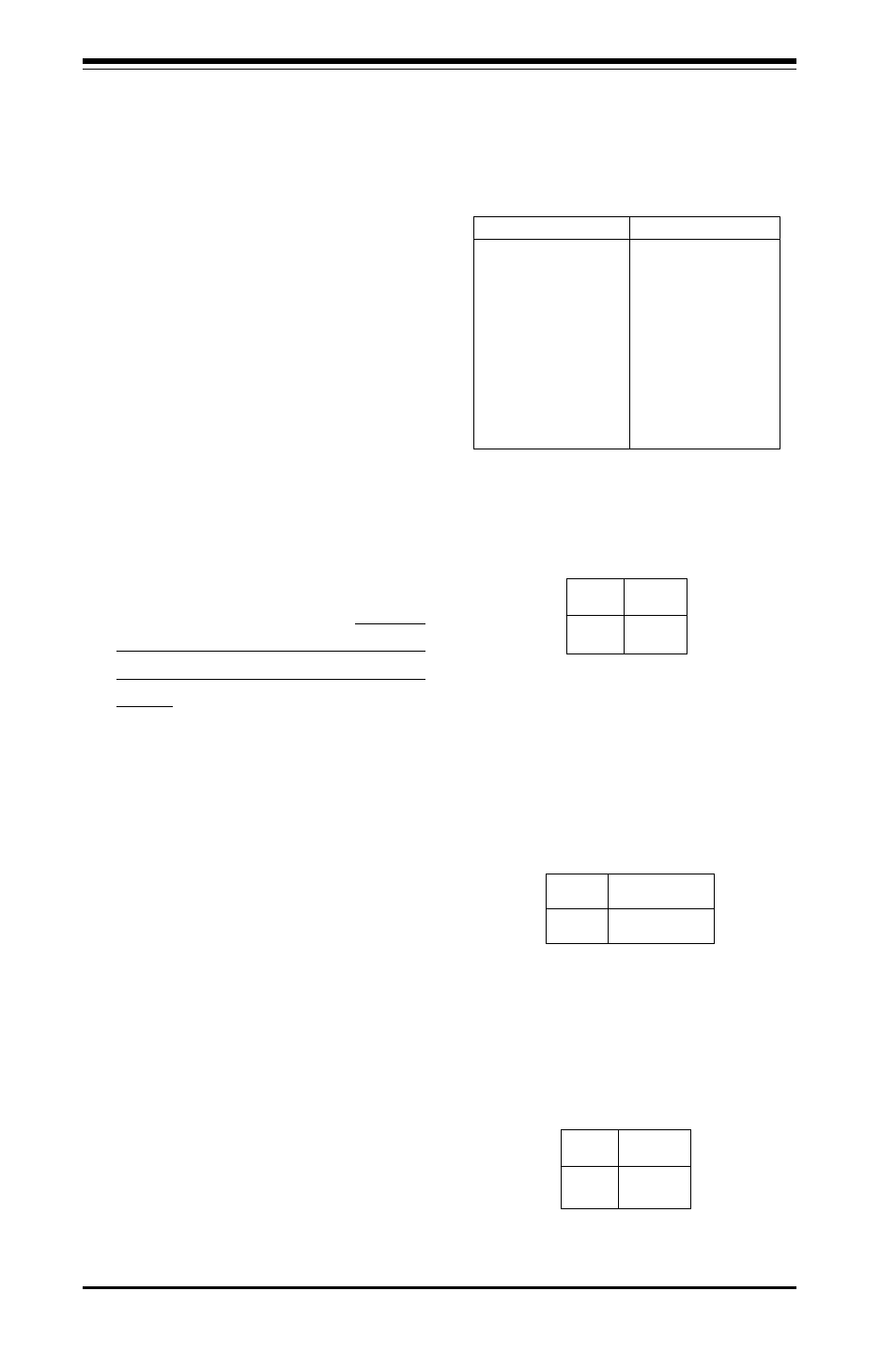
AT X Power Supply 24-pin Connector
Pin Definitio ns
Pin Number Definition
13
+3.3V
14
-12V
15
COM
16
PS_ON#
17
COM
18
COM
19
COM
20
Res(NC)
21
+5V
22
+5V
23
+5V
24
COM
Pin Number Definition
1 +3.3V
2 +3.3V
3 COM
4 +5V
5 COM
6 +5V
7 COM
8 PW R_OK
9
5VSB
10
+12V
11
+12V
12
+3.3V
HDD LED
The HDD LED (for IDE Hard Disk
Drives) connection is located on
pins 13 and 14 of JF1. Attach the
IDE hard drive LED cable to these
pins to display disk activity. Refer
to the table on the right for pin
definitions.
(ID E ) H D D L E D P in
D e fin itio n s
(J F 1 )
P in
N u m b e r
1 3
1 4
D e fin itio n
+ 5 V
H D A ctive
ATX Power Connection
T h e p o w e r s u p p l y c o n n e c t o r
meets the SSI (Superset ATX) 24-
pin specification, however it also
supports a 20-pin power supply
connector. Make sure that the ori-
entation of the PS connector is
correct. See the table on the right
for pin definitions.
P in s
1 th ru 4
5 th ru 8
D e fin itio n
G ro u n d
+ 1 2 v
8 -P in + 1 2 v P o w e r S u p p ly
C o n n e c to r (P W R _ S E C )
PWR_SEC Connection
In addition to the primary ATX
power connector (above), the 12V
8-pin PWR_SEC connector must
also be connected to your power
supply. See the table on the right
for pin definitions.