4 i/o ports, Caution – SUPER MICRO Computer SUPERSERVER 6012L-6 User Manual
Page 41
Chapter 5: Advanced Motherboard Setup
5-7
5-4
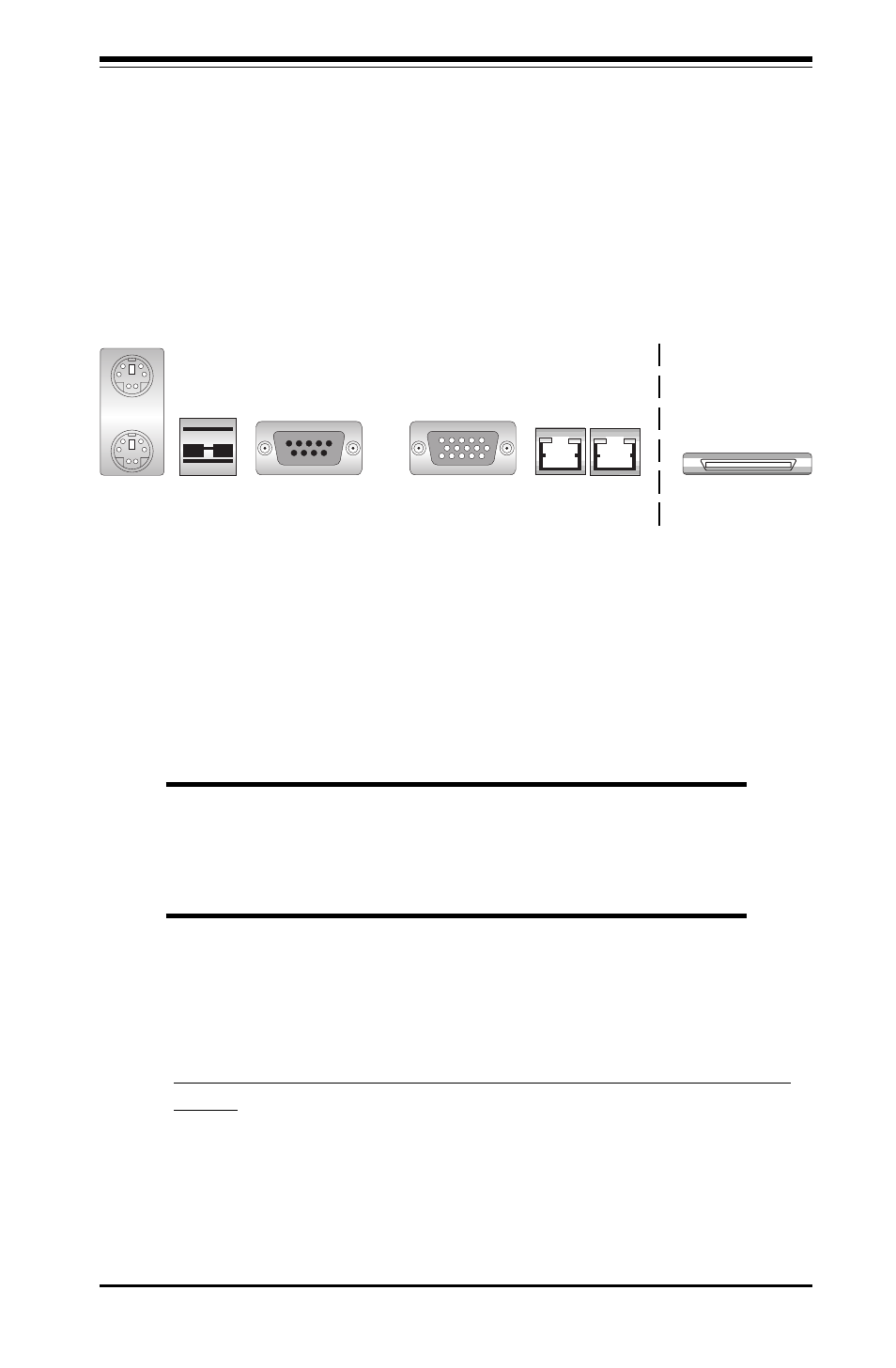
I/O Ports
The I/O ports are color coded in conformance with the PC 99 specification.
See Figure 5-4 below for the colors and locations of the various I/O ports.
Figure 5-4. P4DLR+ Rear Panel I/O Ports
5-5
Installing Memory
Note: Check the Supermicro web site for recommended memory modules:
http://www.supermicro.com/TECHSUPPORT/FAQs/Memory_vendors.htm
CAUTION
Exercise extreme care when installing or removing DIMM
modules to prevent any possible damage. Also note that the
memory is interleaved to improve performance (see step 1).
DIMM Installation (See Figure 5-5)
1. Insert the desired number of DIMMs into the memory slots, starting with
Bank 1 (DIMM#1A, DIMM#1B). The memory scheme is interleaved so
you must install two modules at a time, beginning with Bank 1, then
Bank 2. (See motherboard layout for Bank location.)
2. Insert each DIMM module into its slot. Pay attention to the notch along the
bottom of the module to prevent inserting the DIMM module incorrectly.
3. Gently press down on the DIMM module until it snaps into place in the
slot. Repeat for all modules (see step 1 above). Note that memory
slots are positioned at a 25 degree angle to fit full-sized memory mod-
ules into a 1U chassis.
Keyboard
(Purple)
USB Ports
COM1 Port
(Turquoise)
VGA Port (Blue)
LAN1 LAN2
Mouse
(Green)
External SCSI Port