Alarm interface port, Port and system status leds, Figure 1-2 – SMC Networks SMC TigerAccess SMC7824M/ESW User Manual
Page 25: Port and system leds -5, 5 alarm interface port
D
ESCRIPTION
OF
H
ARDWARE
1-5
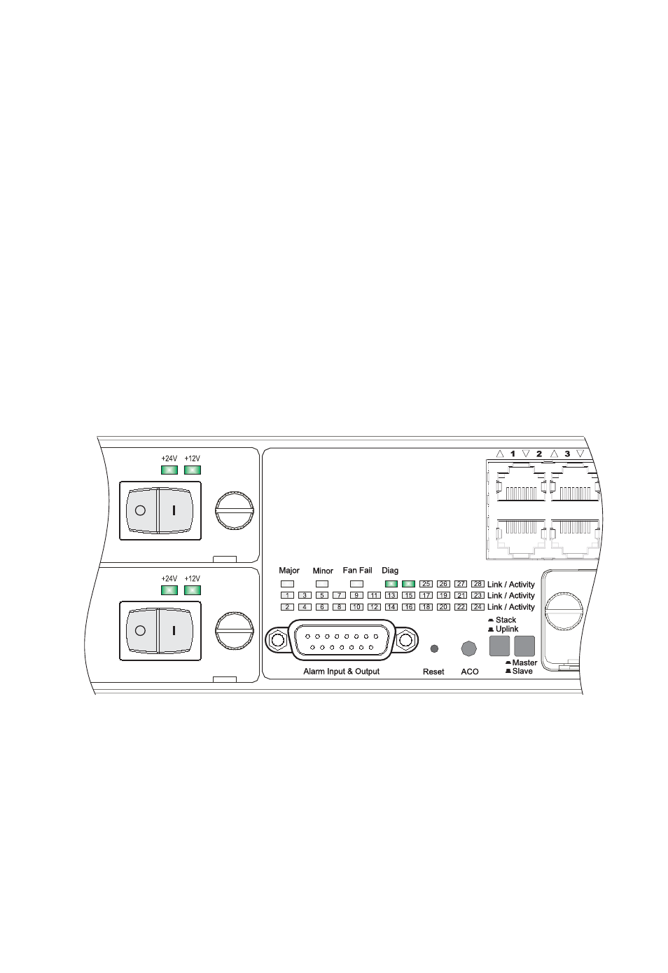
Alarm Interface Port
The DB-15 alarm port on the switch’s front panel can be used to provide
alarm, service port, and BITS clock reference interfaces. The switch
supports two sets of alarm relay contacts (major and minor), and 4 external
customer site alarm inputs. It also provides an alarm cutoff button (labeled
ACO). Refer to “Connecting to the Alarm Port” on page 3-15 for a
description of the pin assignments used to connect to the alarm port.
Port and System Status LEDs
This switch includes a display panel for key system and port indications
that simplifies installation and network troubleshooting. The LEDs, which
are located on the front panel and the power module trays for easy
viewing, are shown below and described in the following tables.
Figure 1-2 Port and System LEDs
Mgmt
Mgmt
- D-P5DW (1 page)
- SMC TigerStack III SMC6824MPE (570 pages)
- 100 (90 pages)
- System 5000 (80 pages)
- D-H7A1 (1 page)
- D-F8B Series (2 pages)
- ES4704BD (2 pages)
- SMC Tiger 10/100 SMC6110L2 (2 pages)
- SMC6708L2 INT (2 pages)
- SMC Tiger 10/100 SMC6128PL2 (664 pages)
- TIGERSWITCH SMC8624T (80 pages)
- SMC EZ Connect SMCUSBH7 (2 pages)
- SMC Tiger 10/100/1000 SMC8124PL2 (2 pages)
- 10G (80 pages)
- 24/16 (31 pages)
- EZ Net 24SW EZNET-24SW (2 pages)
- SMC TigerStack SMC6248M (522 pages)
- SMC-EZ1026DT (2 pages)
- SMC TigerStack 1000 SMC8724M (592 pages)
- SMC TigerCard 10G (86 pages)
- SMC TigerStack 1000 SMC8728L2 (2 pages)
- SMC-EZ108DT (2 pages)
- D-R K Series (8 pages)
- Reed Switch Solid State Switches (27 pages)
- TigerAccess SMC7816VSW (962 pages)
- 100BASE-TX (384 pages)
- TIGERSTACK II SMC8926EM (76 pages)
- SMC6152L2 (2 pages)
- SMC Tiger 10/100 SMC6128L2 (606 pages)
- ETHERNET/IP EX500-AP -S (19 pages)
- SMCGS16-Smart (56 pages)
- SMC TigerAccess SMC7824M/FSW (748 pages)
- TigerStack 100 1000BASE-X (178 pages)
- SMC-EZ1016DT (2 pages)
- VDSL2 (96 pages)
- SMC1016FDT (4 pages)
- SMC TigerStack 1000 SMC8748ML3 (2 pages)
- TigerSwitch 100 (334 pages)
- SMC EZ 10/100/1000 SMCGS8P-Smart (366 pages)
- Edge-core ES4710BD (2 pages)
- SMC EZ Stack 10/100 SMC5216 (2 pages)
- 10/100 (86 pages)
- SMCRPS600W* (78 pages)
- FY100 (22 pages)