2 burner and nozzle characteristics table, Hob burner layout, Instructions for the installer – Smeg A5-6 User Manual
Page 9: 3 hob burner layout, G30/g31, Mbar, Natural gas
Instructions for the Installer
3.2 Burner and nozzle characteristics table
Burner
Rated
heating
capacity
(kW)
LPG
–
G30/G31
28/37
mbar
(drawing ref. X238)
Nozzle
diameter
1/100 mm
By-pass
Mm
1/100
Reduced
flowrate
(W)
Flowrate
g/h G30
Flowrate
g/h G31
Auxiliary
1.05
50
30
360
76
75
Semi rapid
1.8
65
33
450
131
129
Rapid
3.0
85
45
750
218
215
Fish Burner
1.9
68
45
800
138
136
Ultra rapid
3.9
100
68
1600
262
257
UR2 Inner ring
1.0
46
30
350
73
71
UR2 Outer ring
3.5
68+68
68
1600
284
250
Burner
Rated
heating
capacity
(kW)
NATURAL GAS –
G20
20
mbar
Nozzle diameter
1/100 mm
Drawing
Ref.
Reduced flowrate
(W)
Auxiliary
1.05
72
(X)
360
Semi rapid
1.8
97
(Z)
450
Rapid
3.0
115
(Y)
750
Fish Burner
1.9
94
(X)
800
Ultra rapid
3.9
126
(K)
1600
UR2 Inner ring
1.0
70
(X)
350
UR2 Outer ring
3.5
102 +102
(Z)
1600
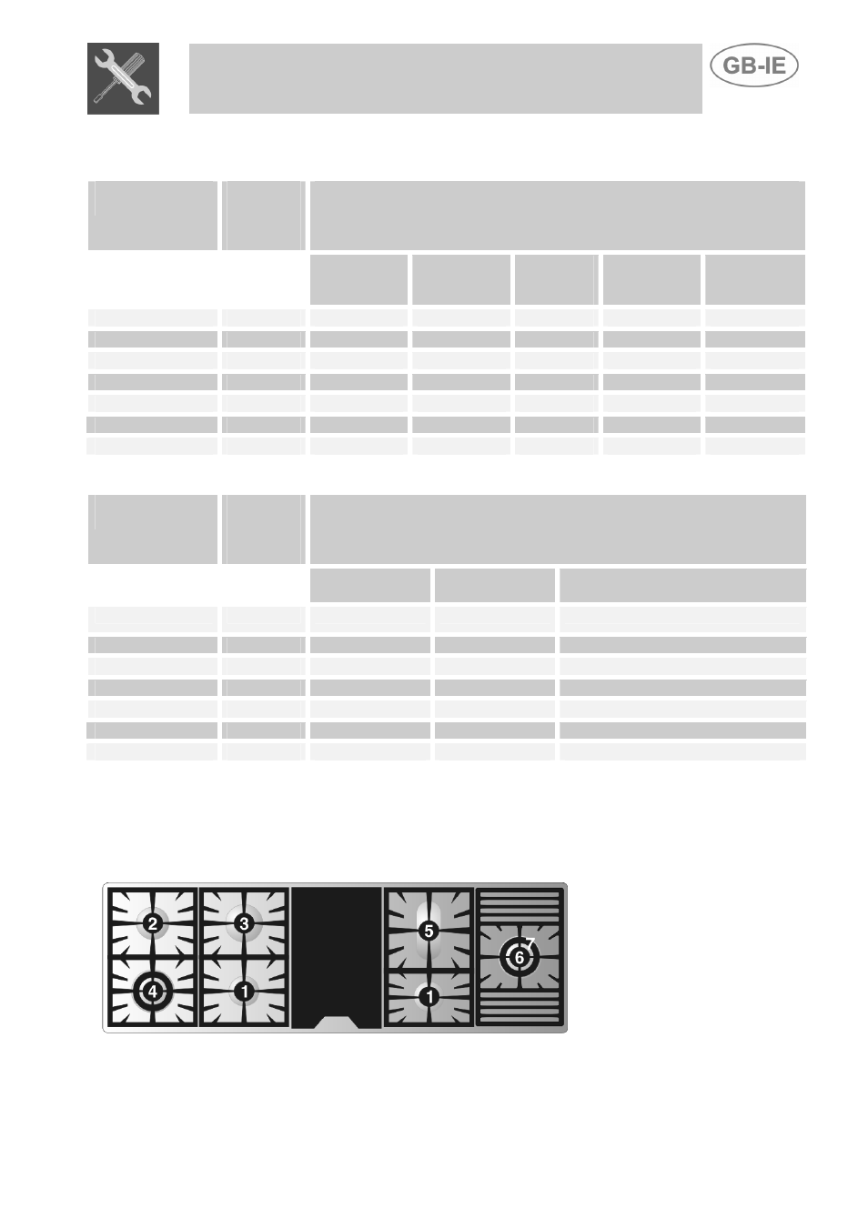
3.3 Hob burner layout
BURNERS
1
Auxiliary
2
Semi rapid
3
Rapid
4
Ultra rapid
5
Fish
6
UR2 Inner ring
7
UR2 Outer ring
51