Spectrum Brands MC.31XX User Manual
Page 68
68
MC.31xx Manual
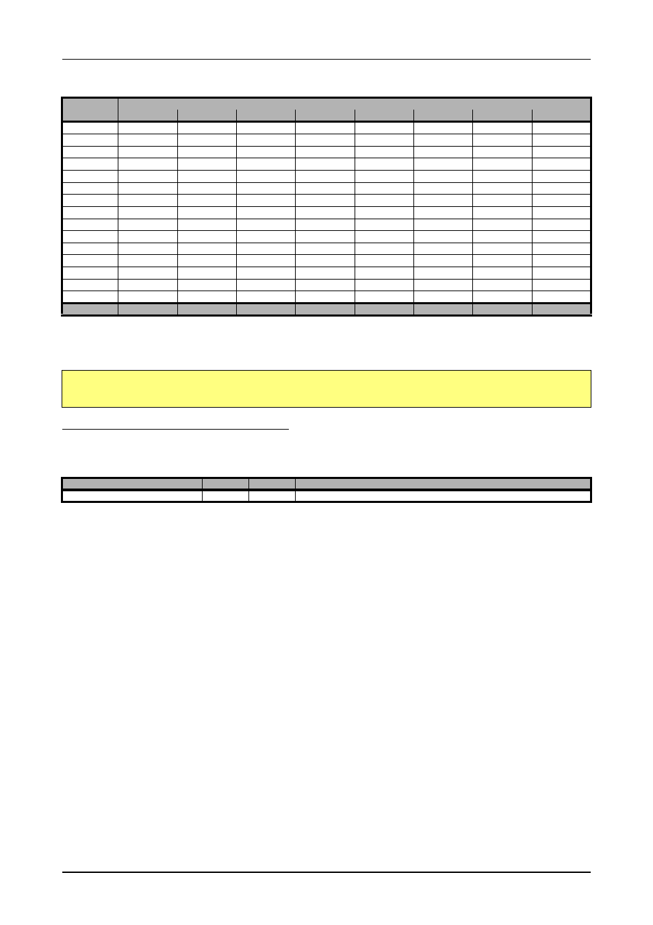
Channel Trigger
Trigger modes and appendant registers
The following example shows, how to set up a one channel board to trigger on channel0’s rising edge. It is asumed, that the input range of
channel0 is set to the the ±200 mV range. The dezimal value for SPC_HIGHLEVEL0 corresponds then with 62.5 mV, wich is the resulting
triggerlevel.
Reading out the number of possible trigger levels
The Spectrum driver also contains a register, that holds the value of the maximum possible different trigger levels considering the above men-
tioned exclusion of the most negative possible value. This is useful, as new drivers can also be used with older hardware versions, because
you can check the trigger resolution during runtime. The register is shown in the following table:
In case of a board that uses 8 bits for trigger detection the returned value would be 255, as either the zero and 127 positive and negative
values are possible.
The resulting trigger step width in mV can easily be calculated from the returned
value. It is assumed that you know the actually selected input range.
To give you an example on how to use this formular we assume, that the
±1.0 V input range is selected and the board uses 8 bits for trigger detection.
The result would be 7.81 mV, which is the step width for your type of board withing the actually chosen input range.
Input ranges
Triggerlevel
±50 mV
±100 mV
±200 mV
±500 mV
±1 V
±2 V
±5 V
±10 V
127
+49.6 mV
+99.2 mV
+198.4 mV
+496.1 mV
+992.2 mV
+1.98 V
+4.96 V
+9.92 V
126
+49.2 mV
+98.4 mV
+196.9 mV
+492.2 mV
+984.4 mV
+1.97 V
+4.92 V
+9.84 V
…
64
+25.0 mV
+50.0 mV
+100.0 mV
+250.0 mV
+500.0 mV
+1.00 V
+2.50 V
+5.00 V
…
2
+0.78 mV
+1.56 mV
+3.1 mV
+7.8 mV
+15.6 mV
+31.3 mV
+78.1 mV
+156.3 mV
1
+0.39 mV
+0.78 mV
+1.5 mV
+3.9 mV
+7.8 mV
+15.6 mV
+39.1 mV
+78.1 mV
0
0 V
0 V
0 V
0 V
0 V
0 V
0 V
0 V
-1
-0.39 mV
-0.78 mV
-1.5 mV
-3.9 mV
-7.8 mV
-15.6 mV
-39.1 mV
-78.1 mV
-2
-0.78 mV
-1.56 mV
-3.1 mV
-7.8 mV
-15.6 mV
-31.3 mV
-78.1 mV
-156.3 mV
…
-64
-25.0 mV
-50.0 mV
-100.0 mV
-250.0 mV
-500.0 mV
-1.00 V
-2.50 V
-5.00 V
…
-126
-49.2 mV
-98.4 mV
-196.9 mV
-492.2 mV
-984.4 mV
-1.97 V
-4.92 V
-9.84 V
-127
-49.6 mV
-99.2 mV
-198.4 mV
-496.1 mV
-992.2 mV
-1.98 V
-4.96 V
-9.92 V
Stepsize
0.39 mV
0.75 mV
1.5 mV
3.9 mV
7.8 mV
15.6 mV
39.1 mV
78.1 mV
SpcSetParam (hDrv, SPC_TRIGGERMODE , TM_CHANNEL); // Enable channel trigger mode
SpcSetParam (hDrv, SPC_TRIGGERMODE0, TM_CHXPOS ); // Enable channel trigger mode
SpcSetParam (hDrv, SPC_HIGHLEVEL0 , 40 ); // Sets triggerlevel to 62.5 mV
Register
Value
Direction
Description
SPC_READTRGLVLCOUNT
2500
r
Contains the number of different possible trigger levels.
Trigger step width
Input Rangemax Input Rangemin
–
Number of trigger levels
1
+
-------------------------------------------------------------------------------------------------------------------------------------------------
=
Trigger step width
+1000 mV (-1000 mV)
–
255
1
+
-------------------------------------------------------------------------------------------------------
=