Gas pressure readings, Service notes - gas pressure adjustment, Table 2 - gas pressure requirements – State Industries GP650YTPDT User Manual
Page 18: Gas pressures (cont)
Technical Literature Department
17 of 52
Ashland City, TN © 2008
Servicing should only be performed by a Qualified Service Agent
ULTRA HIGH EFFICIENCY POWER VENT/POWER DIRECT VENT - SERVICE MANUAL
GAS PRESSURES (CONT)
Service Notes - Gas Pressure Adjustment
Manifold gas pressure is factory set and should not be adjusted in the field. If manifold gas
pressure differs greatly from the pressures in Table 2 consider the calibration of the
manometer being used - try a different manometer. Call the technical support phone number
on the water heater label for further assistance if pressures are considerably different.
Table 2 - Gas Pressures
FUEL TYPE
†
MINIMUM SUPPLY
†. Minimum supply gas pressures must be maintained under both load and no load conditions.
MAXIMUM SUPPLY
MANIFOLD
Natural Gas
3.5” W.C. (0.87 kPa)
14.0” W.C. (3.48 kPa)
0.00” to +0.05” W.C.
(0.00 to +0.012 kPa)
Propane Gas
8.0” W.C. (1.99 kPa)
14.0” W.C. (3.48 kPa)
0.00” to +0.05” W.C.
(0.00 to +0.012 kPa)
CHECKING GAS PRESSURES (CONT)
5 Open the supply gas shut off valve - restore
power - start a heating cycle.
6 The rise in manifold pressure and corresponding
drop in supply gas pressure confirms the water
heater’s gas valve is opening and gas is flowing
to the burner.
7 Record the supply and manifold gas pressures
with the water heater firing.
8 Supply gas pressure should not drop below
minimum given in Table 2 below.
9 Manifold gas pressure should be within the range
shown in Table 2 below.
10 Look through the burner view port (page 11)
burner flame should be blue.
11 Shut off power and gas supply - disconnect
manometers - close test port needle valves.
12 Restore power and gas supply. Check for gas
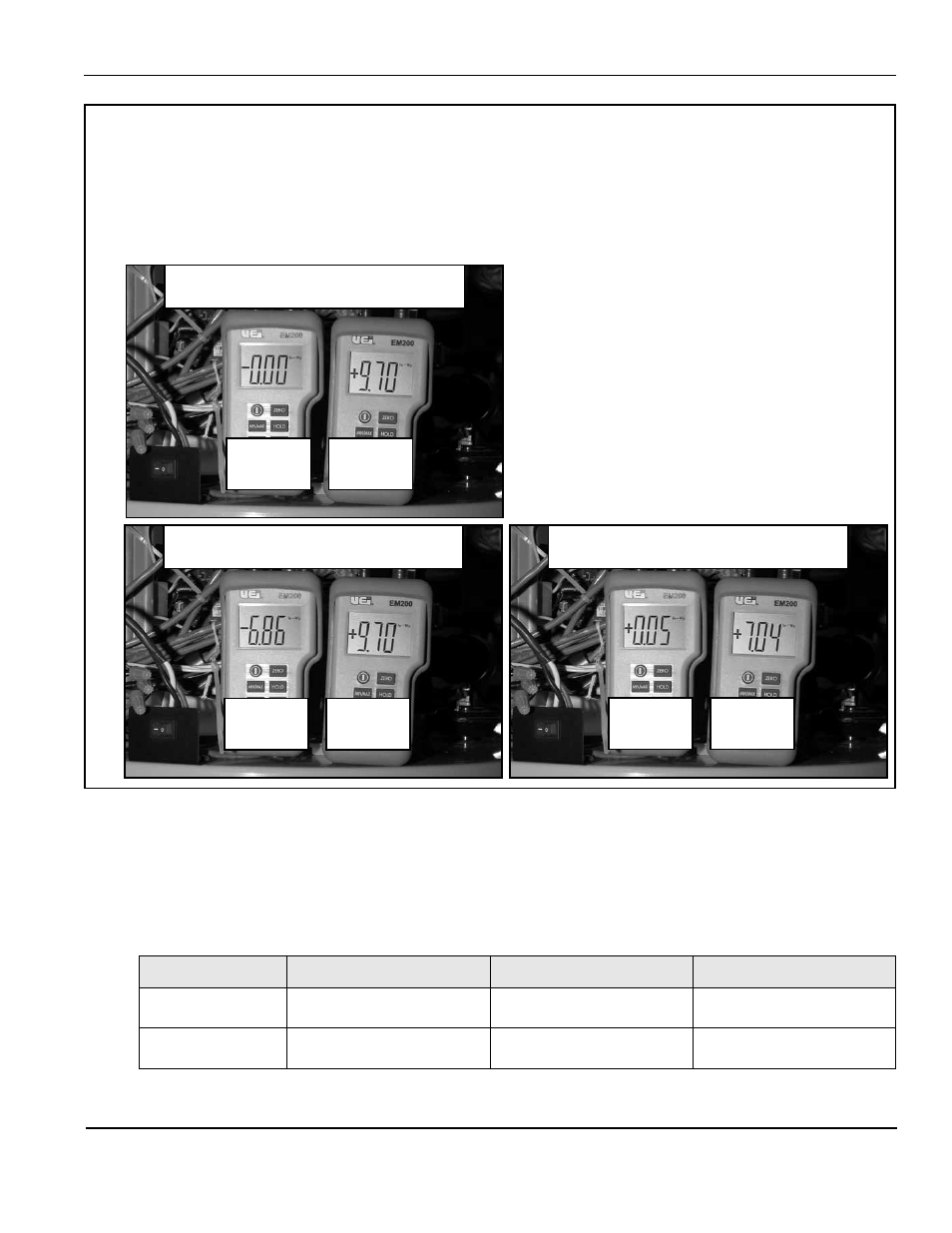
Manifold
Gas
Supply
Gas
Manifold
Gas
Supply
Gas
Manifold
Gas
Supply
Gas
1 BLOWER OFF / GAS VALVE OFF
Manifold 0.00” W.C. Supply +9.70” W.C.
2 BLOWER ON / GAS VALVE OFF
Manifold -6.86” W.C. Supply +9.70” W.C.
3 BLOWER ON / GAS VALVE ON
Manifold +0.05” W.C. Supply +7.04” W.C.
Typical manifold and supply gas pressures during:
1 Standby Mode
2 Pre-Purge Mode
3 Heating Mode