3 connector panel – Sony HDW-F500 User Manual
Page 28
2-3 Connector Panel
2-14
Chapter 2
Locations and Functions of Parts and Controls
Chapter 2
Locations and Functions of Parts and Controls
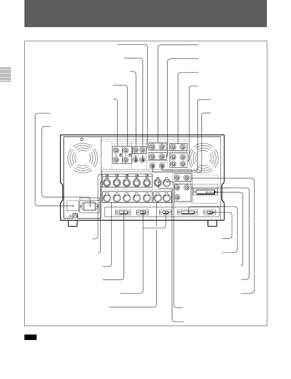
Connector panel
2-3 Connector Panel
8
AUDIO INPUT (AES/EBU)
connectors
9
AUDIO OUTPUT (AES/EBU)
connectors
!º
HD SDI INPUT connectors
!¡
HD SDI OUTPUT connectors
@∞
TIME CODE OUT connector
1
REF. OUT 1125 SYNC connectors
2
D CONV. OUT (OPTION) COMPOSITE
(SUPER) connector
6
BREAKER button
7 ⁄
AC IN connector and
ground connector
!¢
AUDIO INPUT LEVEL/
600
Ω
termination switches
Note
For the AUDIO INPUT CH1/2/3/4 CUE connectors,
AUDIO OUTPUT CH1/2/3/4/CUE connectors, as well
as the TIME CODE IN/OUT (XLR, 3 pins)
connectors, the type (male or female) of input/output
connectors used overseas are opposite of those used in
Japan. To use this unit with audio equipment outside
of Japan, you must use male/female adapters.
3
D CONV. OUT (OPTION) SYNC connector
4
REF. IN SD connectors and 75
Ω
termination switch
5
REF. IN HD connectors and 75
Ω
termination switch
!™
SDTI (OPTION) IN connector
!£
SDTI (OPTION) OUT
connector
!∞
AUDIO INPUT connectors
!§
AUDIO OUTPUT connectors
!¶
CONTROL PANEL connector
!•
REMOTE1-IN(9P)/OUT(9P) connectors
!ª
MONITOR OUTPUT connectors
@º
VIDEO CONTROL
connector
@¡
RS-232C connector
@™
PARALLEL I/O (50P) connector
@§
TIME CODE IN connector
@£
D CONV. SDI OUT (OPTION)
connectors
@¢
PULL DOWN OUT (OPTION)
connector