1-1 upper control panel, 1 control panel – Sony HDW-F500 User Manual
Page 16
2-1 Control Panel
2-2
Chapter 2
Locations and Functions of Parts and Controls
Chapter 2 Locations and Functions of Parts and Controls
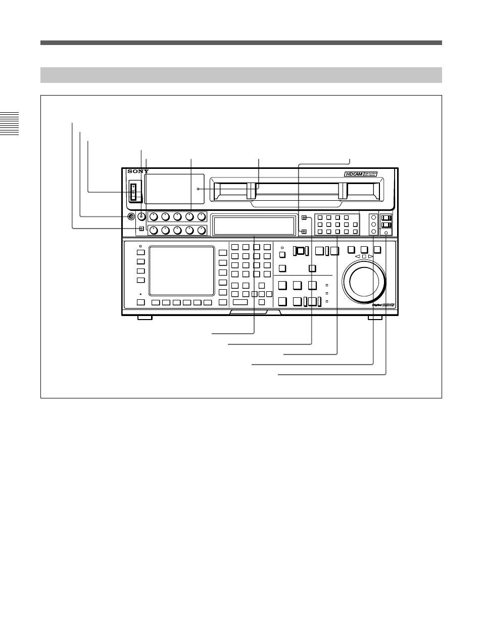
2-1-1 Upper Control Panel
Upper control panel
1 DISPLAY FULL/FINE button
Changes the display range of the audio level meters.
FULL: Display range is –60 to 0 dB (peak level = 0
dB) or –40 to +20 dB (peak level = +20 dB).
Use 814. LEVEL METER SCALE in the VTR
SETUP menu to select the range.
FINE: Displays the audio level in 0.25 dB
increments. The center LED lights up in each
meter as a signal level reference. When the level
exceeds the maximum display value, the top LED
flashes. When the level falls below the minimum
display value, the bottom LED flashes.
2 PHONES jack
Connects stereo headphones with 8
Ω
impedance for
audio monitoring during recording, playback, and
editing. Adjust the headphone output level with the
PHONES level control.
3 POWER switch
Turns on the power. When the power is turned on, the
audio level meters and menu display in the lower
control panel light up.
DIGITAL VIDEO CASSETTE RECORDER HDW-F500
!£
REMOTE buttons and RS-232C indicator
!™
REFERENCE signal indicators
!¡
AUDIO INPUT/MONITOR SELECT buttons
!º
INPUT SELECT button
8
MONITOR SELECT button
1
DISPLAY FULL/FINE button
2
PHONES jack
3
POWER switch
4
PHONES level control
5
PB level
controls
6
REC level controls
7
Audio level meters
9
Indicator window