Chapter 11 gpio usage table, Datasheet – SMSC USB97C242 User Manual
Page 22
USB 2.0 Flash Drive Controller
Datasheet
SMSC USB97C242
Page 22
Revision 1.4 (05-03-07)
DATASHEET
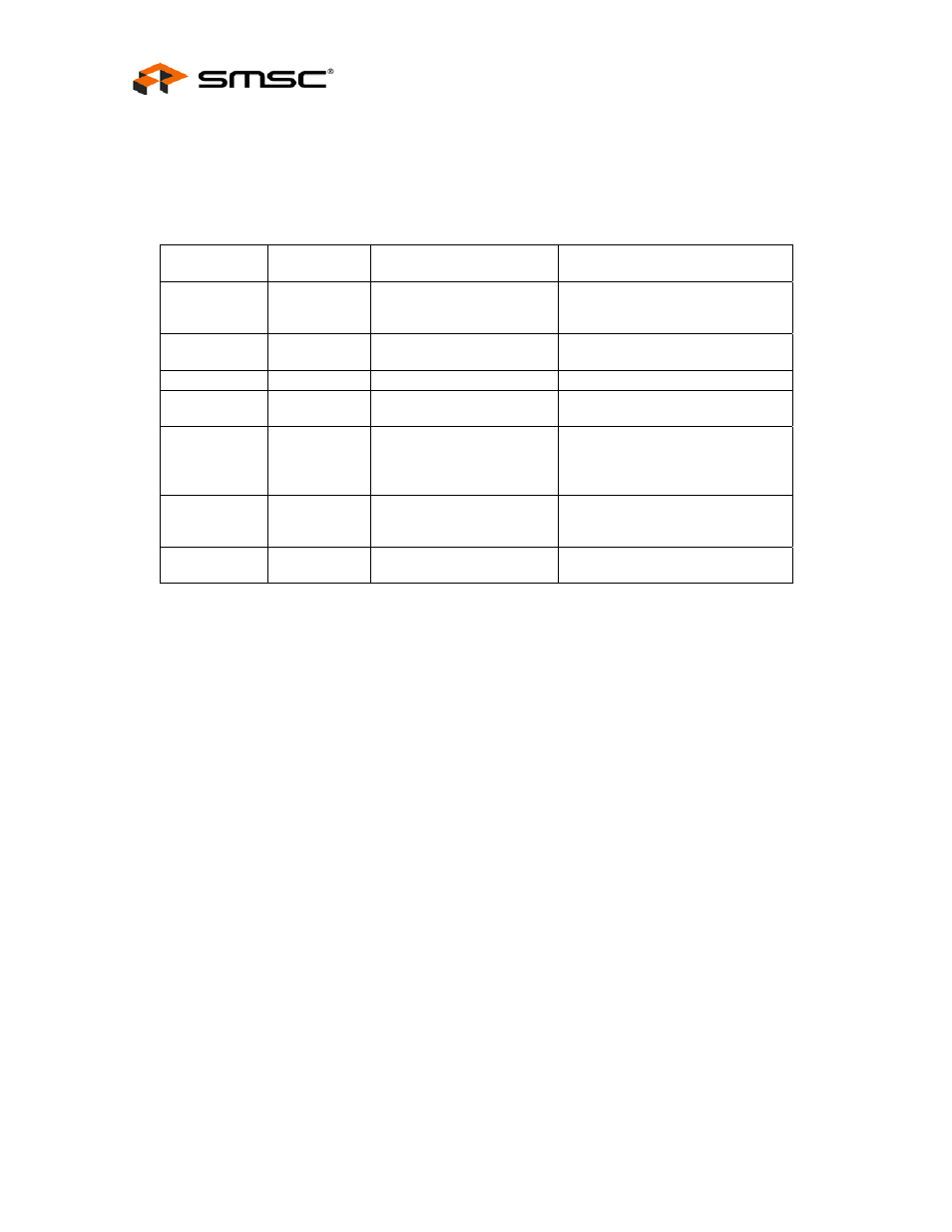
Chapter 11 GPIO Usage Table
Table 11.1 - GPIO Usage
NAME
ACTIVE
LEVEL
SYMBOL
DESCRIPTION AND NOTE
GPIO1
H
Flash Media Activity LED
Indicates media activity. Media or
USB cable must not be removed
with LED lit. Active High.
GPIO2
H
Ready/Busy# 1/4
Ready/Busy# line from NAND
Flash chips 0, or 0 & 4
GPIO3
H
V_BUS
USB V bus dectect
GPIO4
H
Ready/Busy# for Chips 1/5
Ready/Busy# line from NAND
Flash chips 1, or 1 & 5
GPIO5 H
HS_IND/Ready/Busy#
2/6
In Rom -03; HS_LED output
indicator; in later ROM patterns,
the Ready/Busy# line from NAND
Flash chips 2, or 2 & 6
GPIO6
H
A16
A16 address line when external
Rom is used; unused output
otherwise.
GPIO7
H
Ready/Busy# 3/7
Ready/Busy# line from NAND
Flash chips 3, or 3 & 7