Datasheet – SMSC USB97C242 User Manual
Page 13
USB 2.0 Flash Drive Controller
Datasheet
SMSC USB97C242
Page 13
Revision 1.4 (05-03-07)
DATASHEET
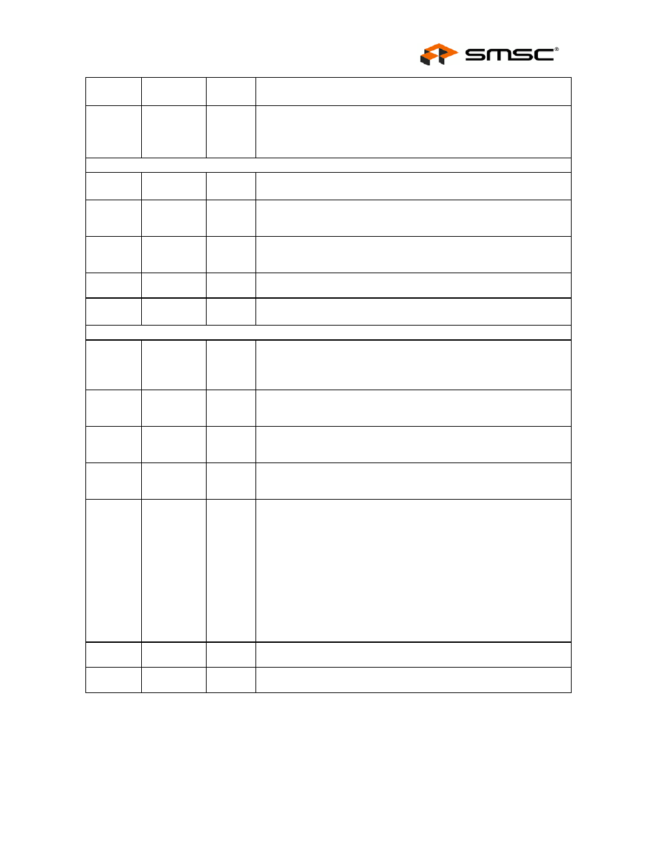
NAME
SYMBOL
BUFFER
TYPE
DESCRIPTION
SM
Card
Detection
nCD
IPU
This is the card detection signal from SM device to indicate if the device
is inserted.
This pin has internal weak pull-up resistor.
USB INTERFACE
USB Bus
Data
USB-
USB+
I/O-U
These pins connect to the USB bus data signals.
USB
Transceiver
Filter
LOOPFLTR
This pin provides the ability to supplement the internal filtering of the
transceiver with an external network, if required.
USB
Transceiver
Bias
RBIAS
A precision 9.09K resistor is attached from ground to this pin to set the
transceiver’s internal bias currents.
Termination
Resistor
RTERM
A precision 1.5K resistor is attached to this pin from a 3.3V supply.
Full Speed
USB Data
FS-
FS+
I/O-U
These pins connect to the USB- and USB+ pins through 31.6 ohm series
resistors.
MEMORY/IO INTERFACE
Memory
Data Bus
MD[7:0]
I/OPU8 When ROMEN = 0, these signals are used to transfer data between the
internal CPU and the external program memory.
When ROMEN = 1, internal weak pull up are activated to prevent these
pins from floating.
Memory
Address
Bus
MA[15:0]
O8
These signals address memory locations within the external memory.
Memory
Read
Strobe
nMWR
O8
Program Memory Write; active low
Memory
Read
Strobe
nMRD
O8
Program Memory Read; active low
Memory
Chip
Enable
nMCE
O8
Program Memory Chip Enable; active low.
This signal shall be de-asserted, when all of the following conditions are
met:
IDLE bit (PCON.0) is 1.
INT2 is negated
SLEEP bit of CLOCK_SEL is 1.
This signal shall be asserted whenever any of the three conditions are
no longer met.
I/O Read
Strobe
nIOR
O8
This is a active low I/O Read strobe signal of Xdata bus.
I/O Write
Strobe
nIOW.
O8
This is a active low I/O Write strobe signal of Xdata bus.