Assembly and adjustments – Skil 3375-01 User Manual
Page 12
12.
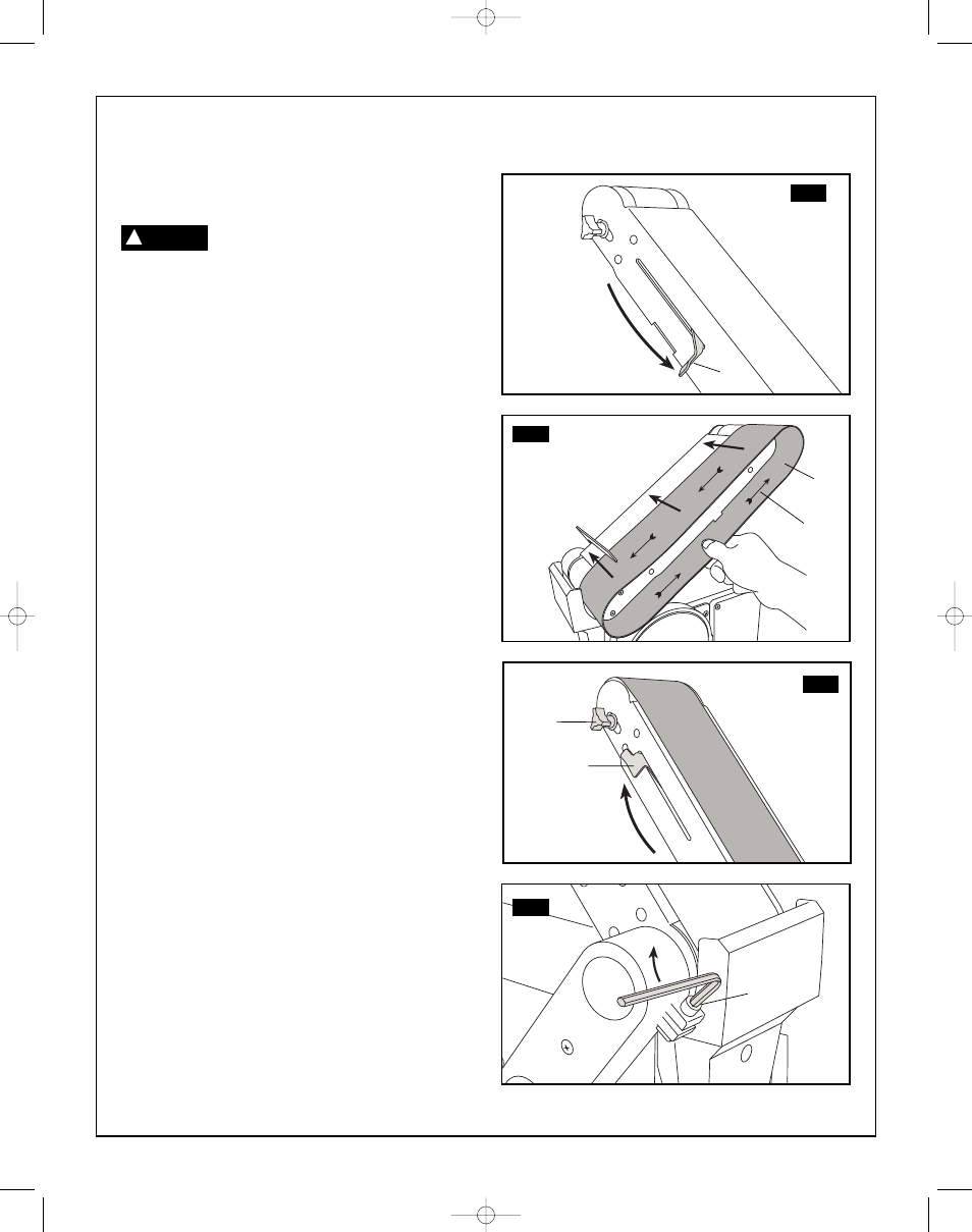
Installing the sanding belt – tensioning
and tracking (Fig. 9-12)
To avoid injury from accidental start,
turn switch ‘OFF’, remove key and
remove plug from power source outlet, before
removing or installing belt.
On the smooth side of the sanding belt, you will find a
‘directional arrow’. The sanding belt must run in the
direction of this arrow, so that the splice does not
come apart.
1. Slide tension lever
(1) to the right to release the belt
tension, as shown in figure 9.
2. Place the sanding belt
(2) over the drums with the
directional arrow
(3) pointing anticlockwise, figure
10. Make sure the belt is centred on both drums.
3. Slide tension lever to the left to apply belt tension,
as shown in figure 11.
4. Tighten hex socket screw
(4) when bed is in
desired position, figure 12.
5. Plug in the power cord. Turn switch ‘On’ and
immediately ‘OFF’, noting if the belt tends to slide
off the idler drum or drive drum. If it did not tend to
slide off it is TRACKING properly.
6. If the sanding belt moves toward the disc, turn the
tracking knob
(5) clockwise 1/4 turn.
7. If the sanding belt moves away from the disc, turn
the tracking knob
(5) anticlockwise 1/4 turn.
8. Turn switch ‘ON and immediately ‘OFF’ noting belt
movement. Readjust tracking knob if necessary.
9. Confirm the maximum gap of 1-2 mm between the
work support and sanding surface, adjust if needed.
Assembly and adjustments
FIG. 11
FIG. 12
FIG. 13
FIG. 14
WARNING
!
1
1
3
2
5
4
SM 2610957110 05-08 6/5/08 7:36 AM Page 12