Assembly and adjustments – Skil 3375-01 User Manual
Page 11
11.
Assembly and adjustments
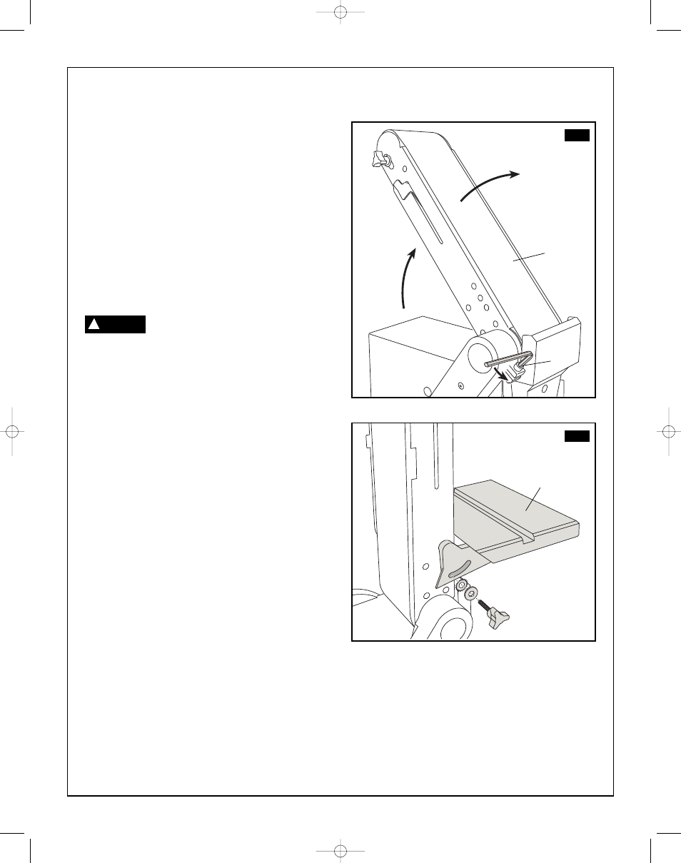
Auxiliary mounting for vertical sanding
(Fig. 7 & 8)
1. Remove work support lock and bolt, and remove
work support.
2. Remove table assembly by removing table lock
knob and washer.
3. Loosen the belt bed locking screw
(1) and raise the
belt sander bed
(2) to the vertical position, figure 7.
4. Retighten the locking screw
(1).
5. Attach work table assembly
(3) to auxiliary holes in
belt bed, figure 8. Make sure index pin is in the
upper hole when sanding table is in vertical
position.
To avoid trapping the work or
fingers between the table and
sanding surface, the table edge should be a
maximum of 1-2 mm from sanding surface.
FIG. 7
FIG. 8
WARNING
!
1
2
3
SM 2610957110 05-08 6/5/08 7:36 AM Page 11