Schneider Electric 174 CEV User Manual
Page 43
Configuring the Bridge
39
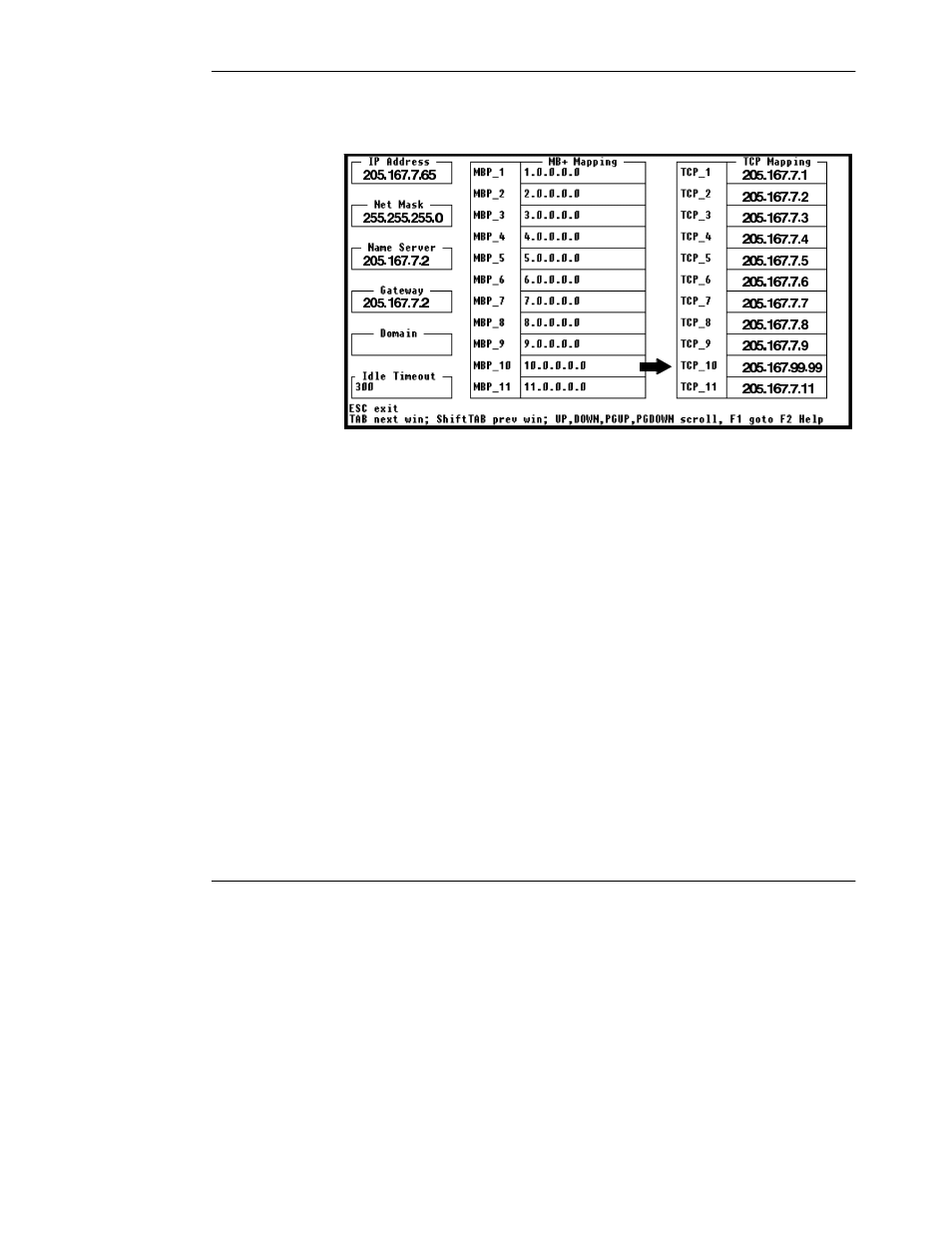
Figure 18 Example: Modbus Plus to TCP/IP Mapping
Use your Tab key to select the TCP Mapping table. Use your cursor ‘arrow’ keys,
Page Up, and Page Down to scroll through the table. F2 displays Help.
3.8.2
Entry Example: TCP Mapping Table
In Figure 18, location TCP_10 shows an example of an entry for custom routing.
Note that location TCP_10 is indexed by the bridge when it receives a message
from a Modbus Plus node with contents 10 in the Modbus Plus routing path byte 3.
The bridge extracts the IP address 205.167.99.99 at the table location, and routes
the message to that IP address.
3.8.3
Saving the Mapping
When you finish setting up the mapping fields for your application, press Escape.
You will be prompted:
Write files to disk?
Enter Y to save the configuration. Two files will written into the bridge’s root
directory. The TCP/IP configuration will be written to the file C:\WATTCP.CFG.
The MB+ and TCP address mapping tables will both be written to C:\RTE.CFG.
You can now use the bridge in your application.