Schneider Electric 174 CEV User Manual
Page 41
Configuring the Bridge
37
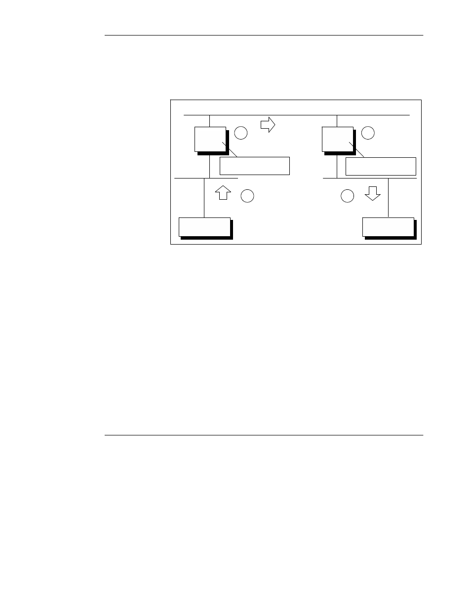
Figure 17 shows an example of the mapping of a message between two
Modbus Plus nodes through a pair of Ethernet bridges.
Figure 17 Example: Linking Modbus Plus Networks Through Ethernet Bridges
Bridge
Bridge
Modbus
Plus
Ethernet
Originating
Node
Destination
Node
Node 25
Node 12
Routiing: 25.8.17.33.0
IP: 205.167.8.10
Modbus
Plus
TCP
Map Entry:
TCP_17: 205.167.8.10
MBP_33: 12.0.0.0.0
Modbus Plus
Map Entry:
A
B
C
D
1
2
A. The Message is Originated
A Modbus Plus node originates a message with the five--byte Modbus Plus path
25.8.17.33.0. The message is addressed to the bridge at node address 25,
specified in the first routing byte.
Bridge 1 (node 25) receives the message and opens its internal path 8. This path
is specified in the second routing byte.
B. Bridge 1 Maps the Message to TCP/IP
Bridge 1 indexes into its TCP Mapping table at location TCP_17, specified by the
third routing byte. Location 17 contains the IP address 205.167.8.10. The bridge
forwards the message to this IP address, a second bridge.
C. Bridge 2 Maps the Message to Modbus Plus
Bridge 2 receives the message and indexes into its Modbus Plus Mapping table at
location MBP_33, specified by the fourth byte of routing in the original message.
Location 33 contains the Modbus Plus routing path 12.0.0.0.0 to a node on the
Modbus Plus network at Bridge 2.
D. The Message is Delivered
The message is delivered to the destination node 12 on the Modbus Plus network.
The node acts upon the Modbus command embedded in the message.