Schneider Electric 174 CEV User Manual
Page 17
Installing the Bridge Hardware
13
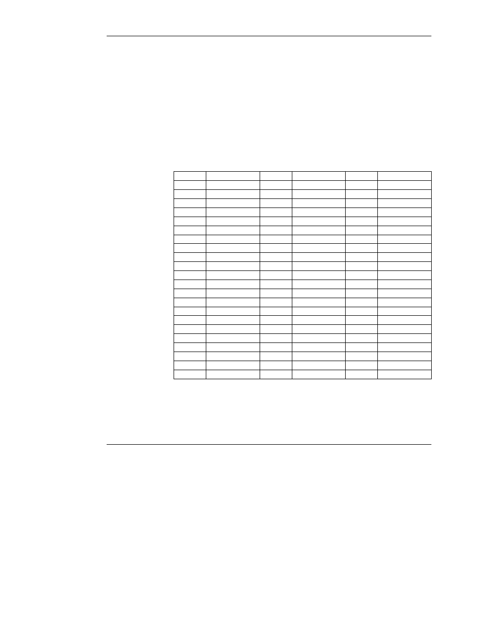
The bridge is shipped with the switches set of a default address of 1 (all switches
in the 0 (zero) position, closest to the card surface).
Set the Modbus Plus address switches 1--6 to the address in your application.
Switches 7 and 8 are not used.
Switch 1 is the least significant bit of the address. Switch 6 is the most significant
bit. The address will be one higher than the binary value you set into the switches.
Table 9 shows the addresses and switch settings.
Table 9 Modbus Plus Addresses and Switch Settings
Address Switches 6--1
Address Switches 6--1
Address Switches 6--1
1
0 0 0 0 0 0
23
0 1 0 1 1 0
45
1 0 1 1 0 0
2
0 0 0 0 0 1
24
0 1 0 1 1 1
46
1 0 1 1 0 1
3
0 0 0 0 1 0
25
0 1 1 0 0 0
47
1 0 1 1 1 0
4
0 0 0 0 1 1
26
0 1 1 0 0 1
48
1 0 1 1 1 1
5
0 0 0 1 0 0
27
0 1 1 0 1 0
49
1 1 0 0 0 0
6
0 0 0 1 0 1
28
0 1 1 0 1 1
50
1 1 0 0 0 1
7
0 0 0 1 1 0
29
0 1 1 1 0 0
51
1 1 0 0 1 0
8
0 0 0 1 1 1
30
0 1 1 1 0 1
52
1 1 0 0 1 1
9
0 0 1 0 0 0
31
0 1 1 1 1 0
53
1 1 0 1 0 0
10
0 0 1 0 0 1
32
0 1 1 1 1 1
54
1 1 0 1 0 1
11
0 0 1 0 1 0
33
1 0 0 0 0 0
55
1 1 0 1 1 0
12
0 0 1 0 1 1
34
1 0 0 0 0 1
56
1 1 0 1 1 1
13
0 0 1 1 0 0
35
1 0 0 0 1 0
57
1 1 1 0 0 0
14
0 0 1 1 0 1
36
1 0 0 0 1 1
58
1 1 1 0 0 1
15
0 0 1 1 1 0
37
1 0 0 1 0 0
59
1 1 1 0 1 0
16
0 0 1 1 1 1
38
1 0 0 1 0 1
60
1 1 1 0 1 1
17
0 1 0 0 0 0
39
1 0 0 1 1 0
61
1 1 1 1 0 0
18
0 1 0 0 0 1
40
1 0 0 1 1 1
62
1 1 1 1 0 1
19
0 1 0 0 1 0
41
1 0 1 0 0 0
63
1 1 1 1 1 0
20
0 1 0 0 1 1
42
1 0 1 0 0 1
64
1 1 1 1 1 1
21
0 1 0 1 0 0
43
1 0 1 0 1 0
22
0 1 0 1 0 1
44
1 0 1 0 1 1
Default Setting
The default setting of the address switches is shown in Section 2.8.