Parallel interface – Star Micronics ATAR LC-500 User Manual
Page 59
– 54 –
APPENDIX
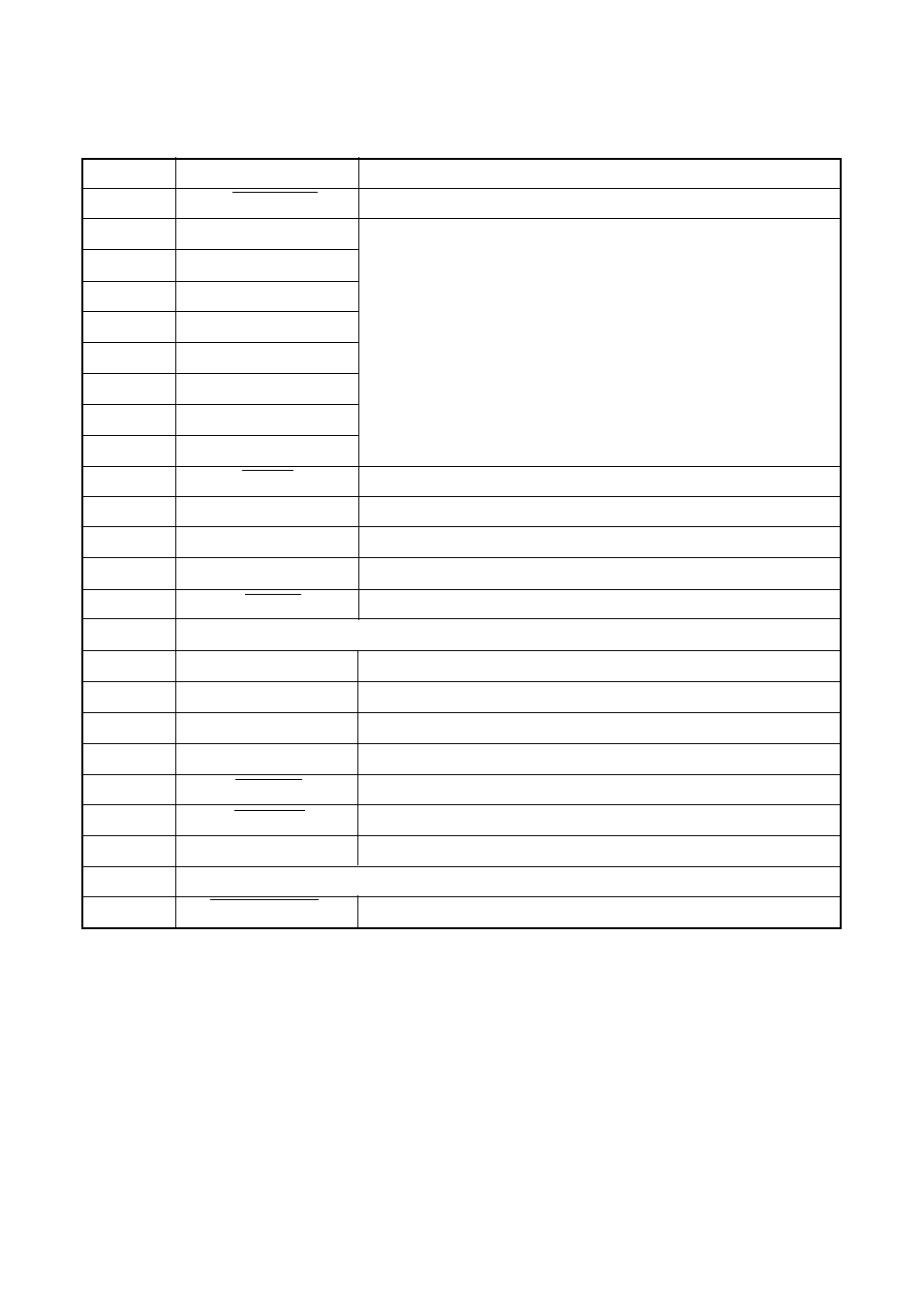
These signals represent information for the 1st
through 8th bit of parallel data, respectively. Each
signal is HIGH when data is logical 1, and LOW
when logical 0.
Parallel Interface
Connector Signals
Pin
Name
Function
1
STROBE
Goes low for
≥
0.5
µ
s when active.
2
DATA0
3
DATA1
4
DATA2
5
DATA3
6
DATA4
7
DATA5
8
DATA6
9
DATA7
10
ACK
10
µ
s low to acknowledge receipt of data.
11
BUSY
Printer sets line low when ready to receive data.
12
PAPER
High when paper runs out.
13
SELECT
High when printer is on-line.
14
AFXT
This signal is used when the mode is nibble mode.
15
Not used.
16
SIGNAL GND
Signal ground
17
CHASSIS
Chassis ground (isolated from signal ground)
18
+5V
+5V DC output from printer
19~30
GND
Twisted pair ground return
31
RESET
Printer is reset when this signal goes low.
32
ERROR
Low when printing cannot continue due to error.
33
EXT GND
External ground
34~35
Not used
36
SELECT IN
This signal is used when the mode is nibble mode.
- LC-90 (131 pages)
- LC-240C (82 pages)
- MP500 Series (2 pages)
- Star SP317 (63 pages)
- SP200F (111 pages)
- NL-10 (35 pages)
- MP115MP-24G-A (42 pages)
- LC-6211 (60 pages)
- 800C (76 pages)
- SLIP SP298 (79 pages)
- LC-1021 (91 pages)
- SP200F SERIES (90 pages)
- SP200F SERIES (114 pages)
- 150 (151 pages)
- LC-1011C (88 pages)
- RS232 (80 pages)
- FUTUREPRINT TSP100 (32 pages)
- SP700 Series (2 pages)
- DP8340RC (40 pages)
- SP342F-A (62 pages)
- PR921-24-A (31 pages)
- SP312F (36 pages)
- SP300 Series (70 pages)
- SP317 (63 pages)
- SP2000 Series (147 pages)
- LC-8021 (86 pages)
- NP-325 (45 pages)
- DP8340 (59 pages)
- PW2000-24 (4 pages)
- HL 80825321 (176 pages)
- Line Thermal Printer (181 pages)
- PUNKT-MATRIX-DRUCKER LC-7211 (182 pages)
- Automatic Sheet Feeder SF-15HA (42 pages)
- Star futurePRNT TSP100GT (2 pages)
- Star SP200 Series (127 pages)
- PT-10Q (36 pages)
- SP298 Series (144 pages)
- LC-8521 (116 pages)
- RSR 28 (5 pages)
- SP320S (94 pages)
- Dot Impact Printer (104 pages)
- LC-4521 (191 pages)
- PT-10Y (32 pages)
- Line Thermal/Dot Printer (209 pages)