6 delayed readout eps and pwc mode, At-140ge – JAI AT-140GE User Manual
Page 49
AT-140GE
- 47 -
Minimum trigger interval is; Exposure time + 1056L(FVAL on normal scan) + 1L
In order to operate this mode, it is recommended to set the shutter speed first at a smaller
value and then a bigger value.
Do not input the trigger signal right after the sequence is reset. At least, 500ms duration is
needed. This may cause malfunction.
ROI can be set for horizontal direction by 8 pixels increment. For vertical direction, it is 1
pixel increment.
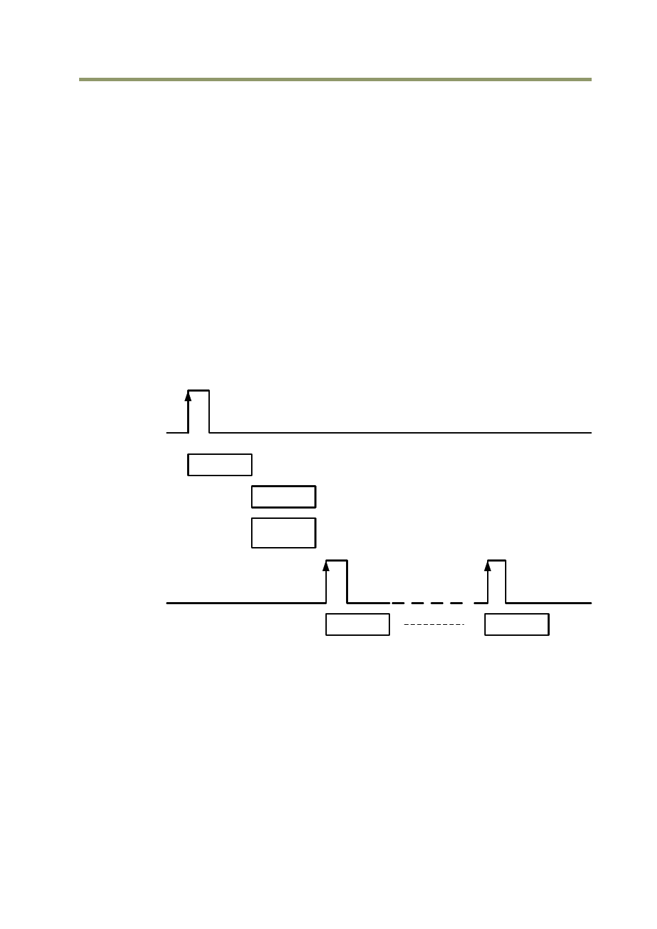
9.7.6 Delayed Readout EPS and PWC Modes (EPS and PWC)
This mode can be used to delay the transmission of a captured image. When several cameras
are triggered simultaneously and connected to the same GigE interface, it allows the cameras
to be read out in sequence, preventing congestion.
The image data is not transmitted directly by the trigger 0 and is stored in the memory
located at the Ethernet Interface. By the falling edge of the soft trigger 1, the image data is
output.
The AT-140GE has up to 4 frames to store, and the stored image data can be output at the
consecutive timing of trigger 1.
This mode can work in EPS mode and PWC mode.
Fig.49 Delayed Read Out Mode
Example of setting
0xA040
PS Delayed Readout (0x17)
0xB060 Trigger 0 select, e.g. 0x04 OPT IN 1
0xB-064 Trigger 1 select, e.g. 0x05 OPT IN 2
For the details of Registers, please refer to the Camera Register Map which is included in the
SDK.
Exposure
CCD output
Store in GigE
memory
Max. 4 frames
GigE output
#1 frame
GigE output
#4 frame
Trigger 0
CCD Surface
CCD transfer path
GigE memory
Trigger 1
RJ45 output