Gpio (general purpose inputs and ou, Overview, 1 lut (look up table) – JAI AT-140GE User Manual
Page 17: At-140ge, Gpio (general purpose inputs and outputs)
AT-140GE
- 15 -
7. GPIO (General purpose inputs and outputs)
In chapter 7, there are some examples of settings. the values shown in these examples
may need to be adjusted to fit the pixel clock specifications of this particular model.
7.1. Overview
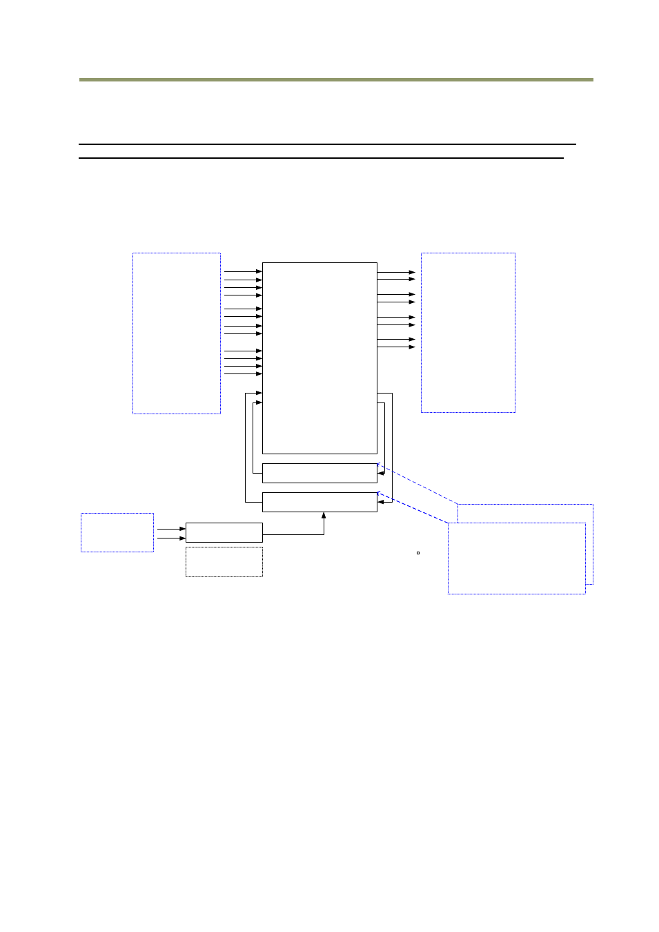
All input and output signals pass through the GPIO (General Purpose Input and Output) module.
The GPIO module consists of a Look-Up Table (LUT – Cross-Point Switch), 2 Pulse Generators
and a 12-bit counter. In the LUT, the relationship between inputs, counters and outputs is
governed by internal register set-up.
On the above block diagram, Trigger 0 is used for Exposure and Trigger 1 is used for Delayed
Readout. The Time Stamp Reset can reset the time stamp in compliance with the GigE Vision
standard. This is used for having the same time stamp in case of using multiple cameras.
The blocks shown in the above diagram have the following functionality:
7.1.1 LUT (Look Up Table)
The LUT works as a cross-point switch, which allows connecting inputs and outputs freely.
The signals LVAL_IN, DVAL_IN, FVAL_IN and EEN_IN all originate from the camera timing
circuit. Trigger 0 is connected to the camera's timing circuit and is used for initiating
triggered exposure. Trigger 1 is used for Delayed Readout mode. The Time Stamp Reset
signal is used to reset the camera's time stamp function, also making it possible to reset and
synchronize the time stamp of multiple cameras.
LUT
( Cross Point Switch )
Pulse Generator 1
(20 bit Counter )
Pulse Generator 0
(20 bit Counter )
12 bit
Counter
TRIGGER 1
TRIGGER 2
TTL OUT 2
OPT OUT 1
OPT OUT 2
Time Stamp Reset
Sequence Reset
LVAL IN
DVAL IN
FVAL IN
EEN IN
OPT IN 1
OPT IN 2
LVDS IN 1
Soft Trigger 0
Soft Trigger 1
Soft Trigger 2
Soft Trigger 3
Pulse trigger IN
Pulse OUT
Pulse Generator 0
Pulse Generator 1
Digital I/O(GPIO) setting
Digital I/O(GPIO) setting
Setting for
Line Source
Setting for
Line Selector
Pixel Clock
Counter Clock Source
1
Counter Divide by value
Bypass
0
1 - 4095
Pulse Generator Setting 0
Start Point Counter 0
Length counter 0
Repeat Counter 0
End point counter 0
Counter 0 clear
Pulse Generator Setting 1
Pulse Generator 1
Pulse Generator 0
TTL IN 1
TTL OUT 1