2 recommended external output circ, 3 optical interface specifications, At-140ge – JAI AT-140GE User Manual
Page 19
AT-140GE
- 17 -
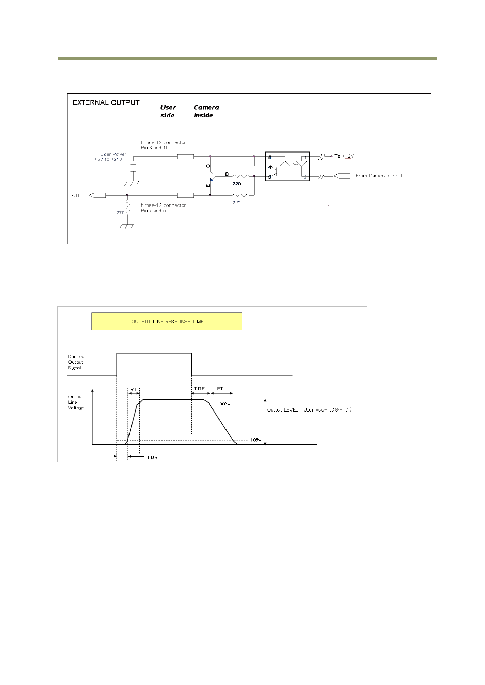
7.2.2 Recommended External Output circuit diagram for customer
Fig.15. External Output Circuit, OPT OUT 1 and 2
7.2.3 Optical Interface Specifications
The relation of the input signal and the output signal through the optical interface is as
follows.
User Power (VCC)
3.3V
5V
12V
24V
Time Delay Rising TDR(µs)
0.54
0.54
0.62
0.68
Rising Time RT(µs)
1.2
1.2
2.0
3.0
Falling Delay Time FDR(µs)
1.5
1.5
2.4
2.1
Falling Time FT(µs)
3.6
3.4
4.5
6.8
Fig.16 Optical Interface Performance