5 sequential trigger mode (eps), At-140ge – JAI AT-140GE User Manual
Page 48
AT-140GE
- 46 -
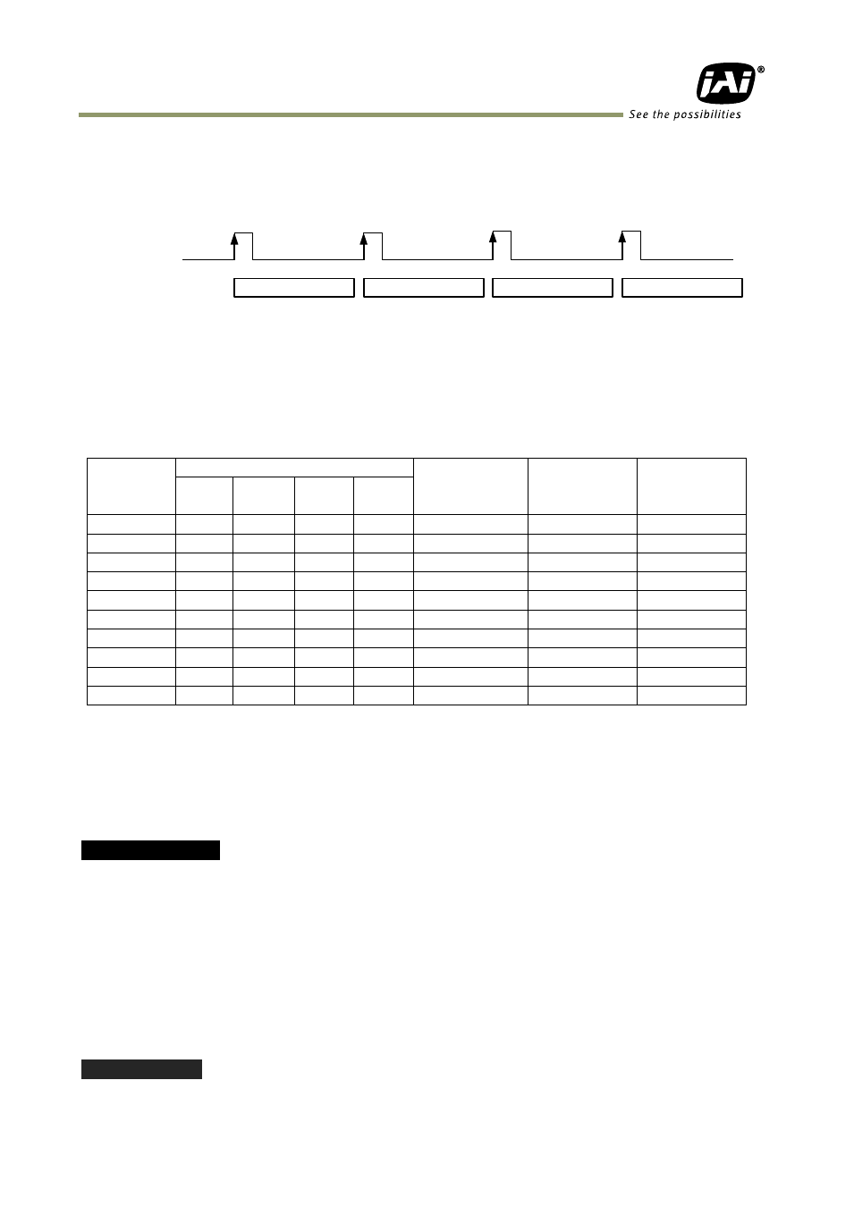
9.7.5 Sequential Trigger Mode (EPS)
This mode allows the user to define a preset sequence of up to 10 images, each with its own
ROI, Shutter and Gain values. As each trigger input is received, the image data with the
preset sequence is output as described below.
Trigger
Sequence
Operation
Fig.48 Sequential Trigger Mode
Signals added to a trigger can be selected by 0xB060 Camera Trigger Selector in the register
map via GPIO. The camera will function on the rising edge of the trigger and Negative or
Positive should be determined accordingly.
The following default settings can be modified by the user to define a sequence.
ID
ROI
Shutter
Gain
Repeat
For each ID
(1 to 50)
Width Height
Offset
X
1
1392
1040
0
1
1056
0
1
2
1392
1040
0
1
1056
0
1
3
1392
1040
0
1
1056
0
1
4
1392
1040
0
1
1056
0
1
5
1392
1040
0
1
1056
0
1
6
1392
1040
0
1
1056
0
1
7
1392
1040
0
1
1056
0
1
8
1392
1040
0
1
1056
0
1
9
1392
1040
0
1
1056
0
1
10
1392
1040
0
1
1056
0
1
The following registers are used to configure the sequence.
0xC0F4 Sequence Repetitions (Number of Repetitions – note: 0 = repeat indefinitely)
0xC0F8 Sequence Ending Position (Ending Position)
0xC0F0 Sequence Reset Command (1 only)
0xB060 Selection for camera trigger 0
0xA040 Trigger mode selection and 0x09 for Sequential PS mode
Example of settings
Setting: Repeat 5 times from ID 1 through ID 8
0xC0F4 Set to 0x05
0xC0F8 Set to 0x08
0xB060 For instance, 12p #6 for Optical IN 1
0xA040 Sequential PS (9)
0xA604 Set video sending flag to1 for start
0xA604 Set video sending flag to 0 for stop
Please refer to the detailed register description on the Camera Register Map which is included
in the SDK.
Important Notes:
Sequence 1
Sequence 4
Sequence 3
Sequence 2